Jeep Parts Wiki | Ford Parts Wiki
Home | Search | Browse
Prev

 Next
Next
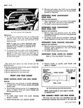
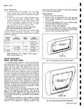
E of the door trim assembly The nails however are pressed or tapped into a new trim assembly plastic retainer which fits into a slot in the door inner panel and firmly holds the door trim assembly in positior fig 10 39 1 TRIM AND ASSEMBLY L i f o Ar o o O PLASTIC RETAINER 1 TRIM RETAINNING WATERPROOF NAIL BODY TAPE V I DOOR TRIM ASSEMBLY Fig 10 39 Door Trim Installation Removal and Installation 1 Apply masking tape to door inner panel at trim assembly retainer locations shown in Figure 10 3E to avoid paint damage when pad is removed 2 With a clean rubber mallet tap around entire edge of trim assembly to free trim nails from plastic retainers 3 Insert a flat bladed tool between inner panel and door trim assembly at each retaining nail location Carefully loosen trim assembly nails from retainer until trim can be removed from door 4 To install reverse removal procedure Broken retaining nails should be replaced with repair tab which are available as service parts CAUTION Retaining nails must not pierce back of plastic retainers as waterleaks may develop l For this reason it is important that PROPER LENGTH repair tab nails l2 are used when replacing broken trim retaining nails If plastic retainers are loose and will not remair engaged in door inner panel install a X piece of cloth backed waterproof body tape over retainer holE in inner panel as shown in View A Figure 10 39 Make two 2 slits in tape to form an X pattern Check retainer for snug fit If retainer is still loose r peat above operation by installing second piece of tape over existing repair This procedure may also be used to repair waterleaks which may develop around perimeter of retainer LOCK STRIKER FRONT AND REAR DOORS Removal and Installation 1 With pencil mark position of striker on body pillar 2 Remove three 3 door lock striker attaching screws and remove striker and adjusting plates from pillar 3 To install seal all striker plate attaching screw clearance holes with body caulking compound 4 Install N bead of body caulking compound around entire back surface of striker plate 5 Place striker and adjusting plates within marks on pillar and install striker plate attaching screws CAUTION Whenever a door has been removed and installed or re aligned the door SHOULD NOT be closed completely until visual check is made to determine if lock extension will engage in striker notch Where required door lock striker emergency spacers should be installed so that door can be closed and an accurate check made to determine emergency spacer requirements 6 Clean off all excess caulking compound f 1 A B Fig 10 40 Determining Door Lock Striker Emergency Spacer Requirements

 Next
Next