Jeep Parts Wiki | Ford Parts Wiki
Home | Search | Browse | Marketplace | Messages | FAQ | Guest
Prev

 Next
Next
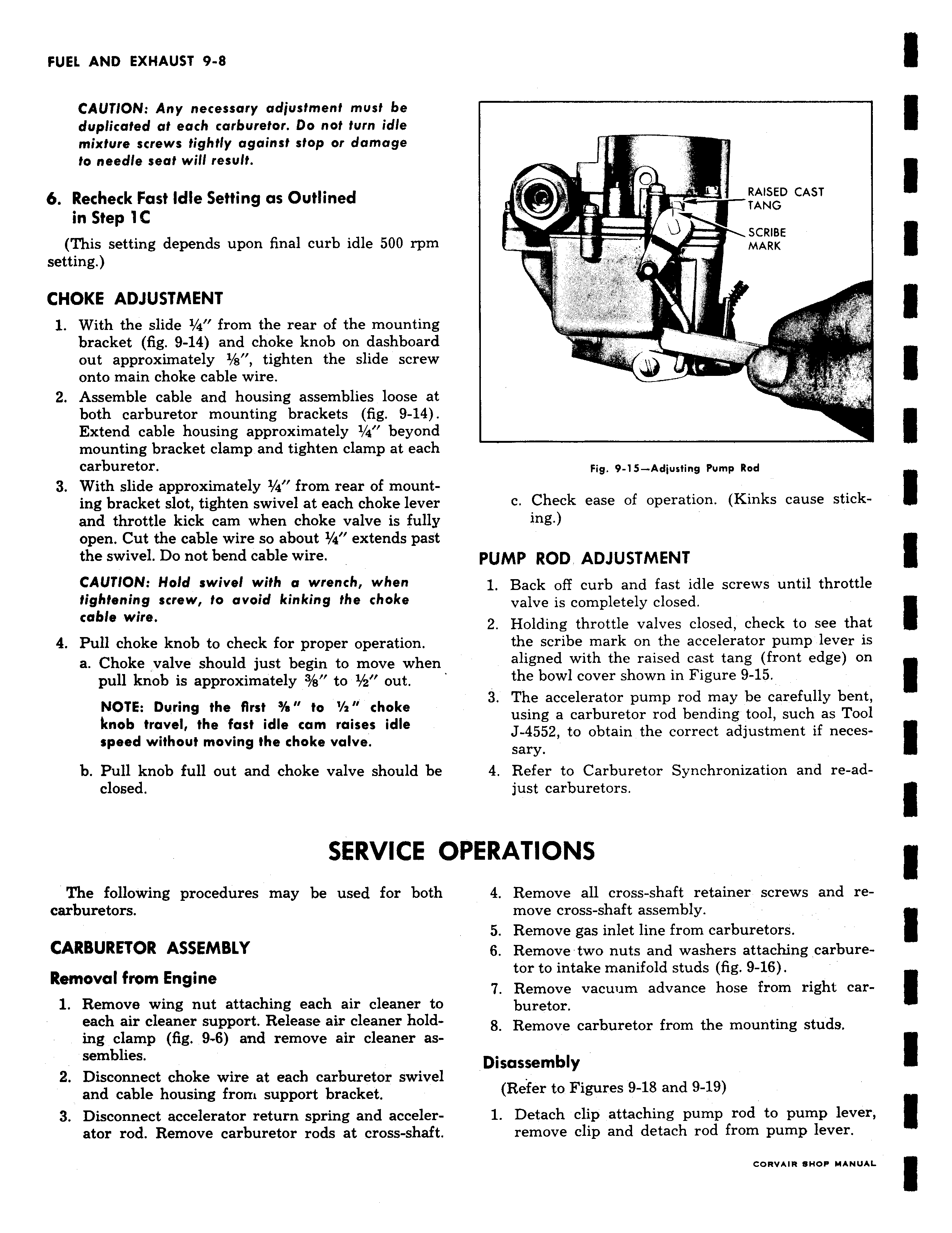
CAUTION Any necessary adjustment must be duplicated at each carburetor Do not turn idle mixture screws tightly against stop or damage to needle seat will result 6 Recheck Fast Idle Setting as Outlined in Step 1 C This setting depends upon final curb idle 500 rpm setting CHOKE ADJUSTMENT 1 With the slide 1 4 from the rear of the mounting bracket fig 9 14 and choke knob on dashboard out approximately 1 s tighten the slide screw onto main choke cable wire 2 Assemble cable and housing assemblies loose at both carburetor mounting brackets fig 9 14 Extend cable housing approximately 1 4 beyond mounting bracket clamp and tighten clamp at each carburetor 3 With slide approximately 1 4 from rear of mounting bracket slot tighten swivel at each choke lever and throttle kick cam when choke valve is fully open Cut the cable wire so about Ya extends past the swivel Do not bend cable wire CAUTION Hold swivel with a wrench when tightening screw to avoid kinking the choke cable wire 4 Pull choke knob to check for proper operation a Choke valve should just begin to move when pull knob is approximately 3 a to 1 z out NOTE During the first s to z choke knob travel the fast idle cam raises idle speed without moving the choke valve b Pull knob full out and choke valve should be closed SERVICE C The following procedures may be used for both carburetors CARBURETOR ASSEMBLY Removal from Engine 1 Remove wing nut attaching each air cleaner to each air cleaner support Release air cleaner holding clamp fig 9 6 and remove air cleaner assemblies 2 Disconnect choke wire at each carburetor swivel and cable housing from support bracket 3 Disconnect accelerator return spring and accelerator rod Remove carburetor rods at cross shaft J O RAISED CAST TANG SCRIBE MARK t Pig 9 15 Adjusting Pump Rod c Check ease of operation Kinks cause sticking PUMP ROD ADJUSTMENT 1 Back off curb and fast idle screws until throttle valve is completely closed 2 Holding throttle valves closed check to see that the scribe mark on the accelerator pump lever is aligned with the raised cast tang front edge on the bowl cover shown in Figure 9 15 3 The accelerator pump rod may be carefully bent using a carburetor rod bending tool such as Tool J 4552 to obtain the correct adjustment if necessary 4 Refer to Carburetor Synchronization and re adjust carburetors iPERATIONS 4 Remove all cross shaft retainer screws and remove cross shaft assembly 5 Remove gas inlet line from carburetors 6 Remove two nuts and washers attaching carburetor to intake manifold studs fig 9 16 Remove vacuum advance hose from right carburetor 8 Remove carburetor from the mounting studs Disassembly Refer to Figures 9 18 and 9 19 1 Detach clip attaching pump rod to pump lever remove clip and detach rod from pump lever

 Next
Next