Jeep Parts Wiki | Ford Parts Wiki
Home | Search | Browse
Prev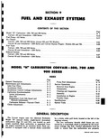
 Next
Next
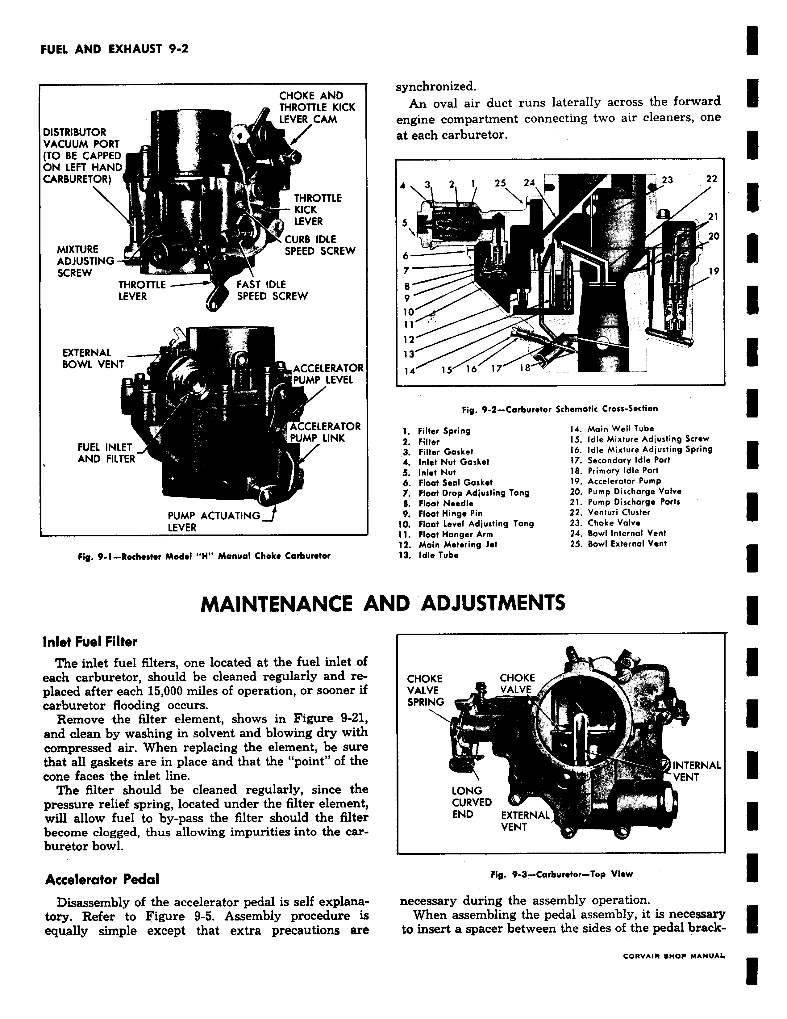
CHOKE AND THROTTLE KICK LEVER CAM DISTRIBUTOR VACUUM PORT TO BE CAPPED ON LEFT HAND CARBURETOR THROTTLE KICK LEVER CURB IDLE MIXTURE W SPEED SCREW ADJUSTING SCREW THROTTLE FAST IDLE LEVER SPEED SCREW EXTERNAL BOWL VENT ACCELERATOR PUMP LEVEL ACCELERATOR PUMP LINK FUEL INLET AND FILTER PUMP ACTUATING LEVER Fig 9 1 Rochester Model H Manual Choke Carburetor MAINTENANCE A Inlet Fuel Filter The inlet fuel filters one located at the fuel inlet of each carburetor should be cleaned regularly and replaced after each 15 000 miles of operation or sooner if carburetor flooding occurs Remove the filter element shows in Figure 9 21 and clean by washing in solvent and blowing dry with compressed air When replacing the element be sure that all gaskets are in place and that the point of the cone faces the inlet line The filter should be cleaned regularly since the pressure relief spring located under the filter element will allow fuel to by pass the filter should the filter become clogged thus allowing impurities into the carburetor bowl Accelerator Pedal Disassembly of the accelerator pedal is self explanatory Refer to Figure 9 5 Assembly procedure is equally simple except that extra precautions are synchronized An oval air duct runs laterally across the forward engine compartment connecting two air cleaners one at each carburetor 4 3 2 1 25 24 L 23 22 1 I 21 I 20 7 19 10 12 13 13 i 14 15 16 171 118 Fig 9 3 Carburetor Schematic Cross Section 1 Filter Spring 14 Main Well Tube 2 Filter 15 Idle Mixture Adjusting Screw 3 Filter Gasket 16 Idle Mixture Adjusting Spring 4 Inlet Nut Gasket 17 Secondary Idle Port S Inlet Nut 18 Primary Idle Port 6 Float Seal Gasket 19 Accelerator Pump 7 Float Drop Adjusting Tang 20 Pump Discharge Volvo 8 Float Needle 21 Pump Discharge Ports 9 Float Hinge Pin 22 Venturi Cluster 10 Float Level Adjusting Tang 23 Choke Valve 11 Float Hanger Arm 24 Bowl Internal Vent 12 Main Metering Jet 25 Bowl External Vent 13 Idle Tuba I ND ADJUSTMENTS CHOKE CHOKE VALVE VALVE SPRING INTERNAL R VENT LONG CURVED END EXTERNAL VENT Fig 9 3 Carburetor Top View necessary during the assembly operation When assembling the pedal assembly it is necessary to insert a spacer between the sides of the pedal brack CORVAIR SHOP MANUAL