Jeep Parts Wiki | Ford Parts Wiki
Home | Search | Browse
Prev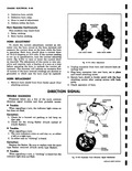
 Next
Next
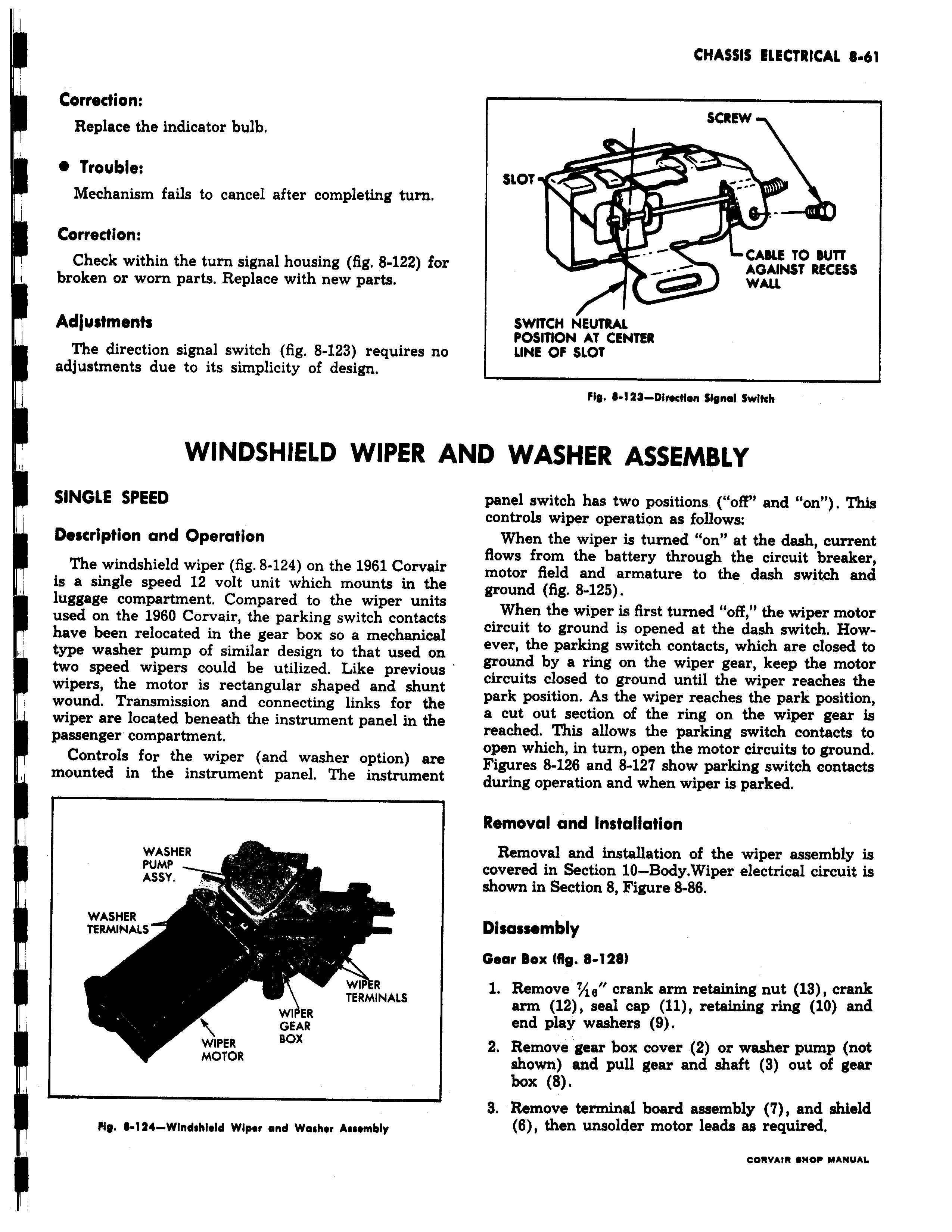
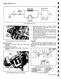
Correction Replace the indicator bulb Trouble Mechanism fails to cancel after completing turn Correction Check within the turn signal housing fig 8 122 for broken or worn parts Replace with new parts Adjustments The direction signal switch fig 8 123 requires no adjustments due to its simplicity of design WINDSHIELD WIPER A SINGLE SPEED Description and Operation The windshield wiper fig 8 124 on the 1961 Corvair is a single speed 12 volt unit which mounts in the 1 luggage compartment Compared to the wiper units 1 used on the 1960 Corvair the parking switch contacts have been relocated in the gear box so a mechanical type washer pump of similar design to that used on two speed wipers could be utilized Like previous wipers the motor is rectangular shaped and shunt wound Transmission and connecting links for the wiper are located beneath the instrument panel in the passenger compartment Controls for the wiper and washer option are mounted in the instrument panel The instrument WASHER PUMP ASSY I WASHER TERMINALS i WR TERMINALS WIPER GEAR WIPER BOX MOTOR HO 124 Windshidd Wiper and Washer Assembly SCREW SLOT r CAKE TO BUTT AGAINST RECESS WALL SWITCH NEUTRAL POSITION AT CENTER LINE OF SLOT Fig 123 Dlrostion signal Swlkh ND WASHER ASSEMBLY panel switch has two positions off and on This controls wiper operation as follows When the wiper is turned on at the dash current flows from the battery through the circuit breaker motor field and armature to the dash switch and ground fig 8 125 When the wiper is first turned off the wiper motor circuit to ground is opened at the dash switch However the parking switch contacts which are closed to ground by a ring on the wiper gear keep the motor circuits closed to ground until the wiper reaches the park position As the wiper reaches the park position a cut out section of the ring on the wiper gear is reached This allows the parking switch contacts to open which in turn open the motor circuits to ground Figures 8 126 and 8 127 show parking switch contacts during operation and when wiper is parked Removal and Installation Removal and installation of the wiper assembly is covered in Section 10 Body Wiper electrical circuit is shown in Section 8 Figure 8 86 Disassembly Gear Box fig 8 128 1 Remove 7 16 crank arm retaining nut 13 crank arm 12 seal cap 11 retaining ring 10 and end play washers 9 2 Remove gear box cover 2 or washer pump not shown and pull gear and shaft 3 out of gear box 8 3 Remove terminal board assembly 7 and shield 6 then unsolder motor leads as required eewmw Awnw UANUm