Jeep Parts Wiki | Ford Parts Wiki
Home | Search | Browse
Prev
 Next
Next
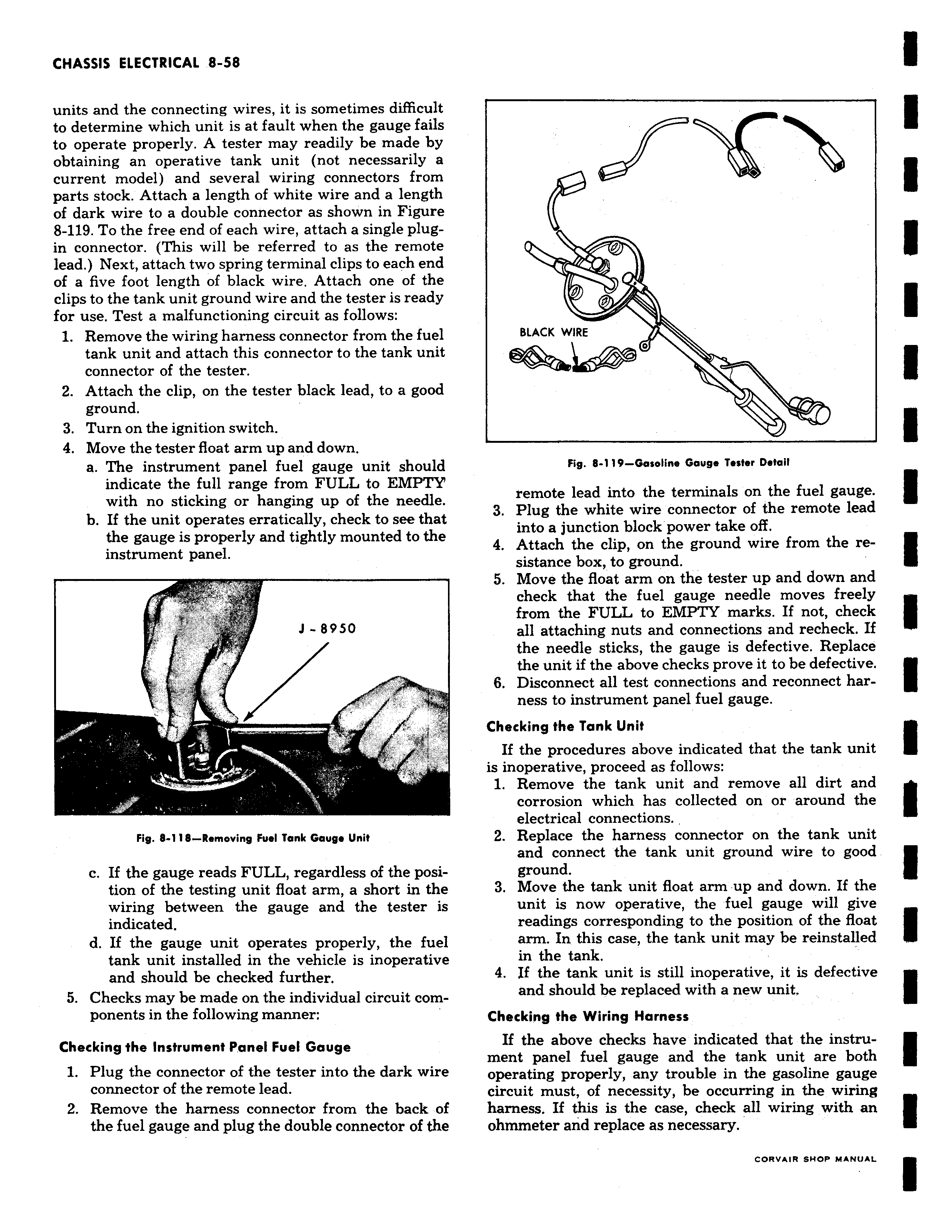
units and the connecting wires it is sometimes difficult to determine which unit is at fault when the gauge fails to operate properly A tester may readily be made by obtaining an operative tank unit not necessarily a current model and several wiring connectors from parts stock Attach a length of white wire and a length of dark wire to a double connector as shown in Figure 8 119 To the free end of each wire attach a single plugin connector This will be referred to as the remote lead Next attach two spring terminal clips to each end of a five foot length of black wire Attach one of the clips to the tank unit ground wire and the tester is ready for use Test a malfunctioning circuit as follows 1 Remove the wiring harness connector from the fuel tank unit and attach this connector to the tank unit connector of the tester 2 Attach the clip on the tester black lead to a good ground 3 Turn on the ignition switch 4 Move the tester float arm up and down a The instrument panel fuel gauge unit should indicate the full range from FULL to EMPTY with no sticking or hanging up of the needle b If the unit operates erratically check to see that the gauge is properly and tightly mounted to the instrument panel J 8950 rr Fig 8 118 Removing Fuel Tank Gauge Unit c If the gauge reads FULL regardless of the position of the testing unit float arm a short in the wiring between the gauge and the tester is indicated d If the gauge unit operates properly the fuel tank unit installed in the vehicle is inoperative and should be checked further 5 Checks may be made on the individual circuit components in the following manner Checking the Instrument Panel Fuel Gauge 1 Plug the connector of the tester into the dark wire connector of the remote lead 2 Remove the harness connector from the back of the fuel gauge and plug the double connector of the 0 0 a BLACK WIRE Lfl Fig 8 119 Gasoline Gauge Tester Detail remote lead into the terminals on the fuel gauge 3 Plug the white wire connector of the remote lead into a junction block power take off 4 Attach the clip on the ground wire from the resistance box to ground 5 Move the float arm on the tester up and down and check that the fuel gauge needle moves freely from the FULL to EMPTY marks If not check all attaching nuts and connections and recheck If the needle sticks the gauge is defective Replace the unit if the above checks prove it to be defective 6 Disconnect all test connections and reconnect harness to instrument panel fuel gauge Checking the Tank Unit If the procedures above indicated that the tank unit is inoperative proceed as follows 1 Remove the tank unit and remove all dirt and corrosion which has collected on or around the electrical connections 2 Replace the harness connector on the tank unit and connect the tank unit ground wire to good ground 3 Move the tank unit float arm up and down If the unit is now operative the fuel gauge will give readings corresponding to the position of the float arm In this case the tank unit may be reinstalled in the tank 4 If the tank unit is still inoperative it is defective and should be replaced with a new unit Checking the Wiring Harness If the above checks have indicated that the instrument panel fuel gauge and the tank unit are both operating properly any trouble in the gasoline gauge circuit must of necessity be occurring in the wiring harness If this is the case check all wiring with an ohmmeter and replace as necessary CORVSIR SHOP MANUAL