Jeep Parts Wiki | Ford Parts Wiki
Home | Search | Browse
Prev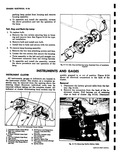
 Next
Next
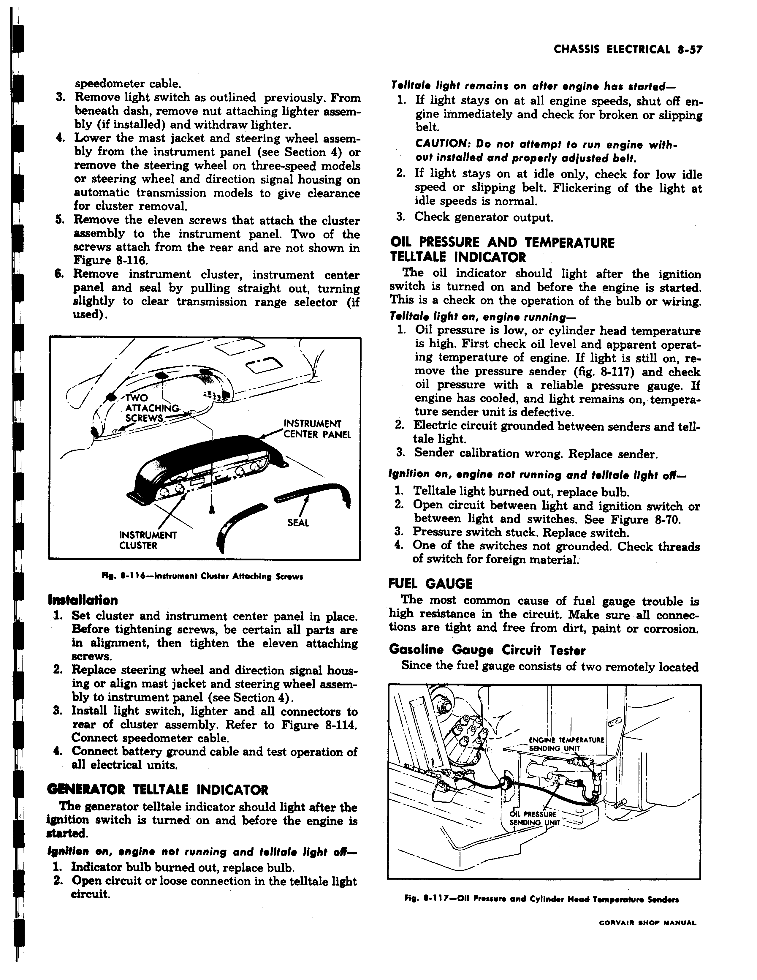
speedometer cable 3 Remove light switch as outlined previously From beneath dash remove nut attaching lighter assembly if installed and withdraw lighter 4 Lower the mast jacket and steering wheel assembly from the instrument panel see Section 4 or remove the steering wheel on three speed models or steering wheel and direction signal housing on automatic transmission models to give clearance for cluster removal I S Remove the eleven screws that attach the cluster assembly to the instrument panel Two of the screws attach from the rear and are not shown in Figure 8 116 6 Remove instrument cluster instrument center panel and seal by pulling straight out turning slightly to clear transmission range selector if used O ATTACHING SCREWS INSTRUMENT CENTER PANEL sh SEAL INSTRUMENT CLUSTER Fig 8 1 16 instrument Cluster Attaching Screws IMtallotion j 1 Set cluster and instrument center panel in place Before tightening screws be certain all parts are in alignment then tighten the eleven attaching screws 2 Replace steering wheel and direction signal housing or align mast jacket and steering wheel assembly to instrument panel see Section 4 S Install light switch lighter and all connectors to rear of cluster assembly Refer to Figure 8 114 Connect speedometer cable Connect battery ground cable and test operation of all electrical units GENERATOR TELLTALE INDICATOR The generator telltale indicator should light after the ignition switch is turned on and before the engine is started IgnNlon on engine not running and telltale light off1 Indicator bulb burned out replace bulb 2 Open circuit or loose connection in the telltale light circuit Telltale light remains on after engine has started 1 If light stays on at all engine speeds shut off engine immediately and check for broken or slipping belt CAUTION Do not attempt to run engine without installed and properly adjusted belt 2 If light stays on at idle only check for low idle speed or slipping belt Flickering of the light at idle speeds is normal 3 Check generator output OIL PRESSURE AND TEMPERATURE TELLTALE INDICATOR The oil indicator should light after the ignition switch is turned on and before the engine is started This is a check on the operation of the bulb or wiring Telltale light on engine running 1 Oil pressure is low or cylinder head temperature is high First check oil level and apparent operating temperature of engine If light is still on remove the pressure sender fig 8 117 and check oil pressure with a reliable pressure gauge If engine has cooled and light remains on temperature sender unit is defective 2 Electric circuit grounded between senders and telltale light 3 Sender calibration wrong Replace sender Ignition on engine not running and telltale light off1 Telltale light burned out replace bulb 2 Open circuit between light and ignition switch or between light and switches See Figure 8 0 3 Pressure switch stuck Replace switch 4 One of the switches not grounded Check threads of switch for foreign material FUEL GAUGE The most common cause of fuel gauge trouble is high resistance in the circuit Make sure all connections are tight and free from dirt paint or corrosion Gasoline Gauge Circuit Tester Since the fuel gauge consists of two remotely located ENGINE TE i EMATURE v ENDING UNIT IL PRESSURE SENDING UNIT Fig 111 1117 00 Pressure and Cylinder Head Temperature Senders r nwm awm u wuu