Jeep Parts Wiki | Ford Parts Wiki
Home | Search | Browse
Prev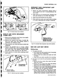
 Next
Next
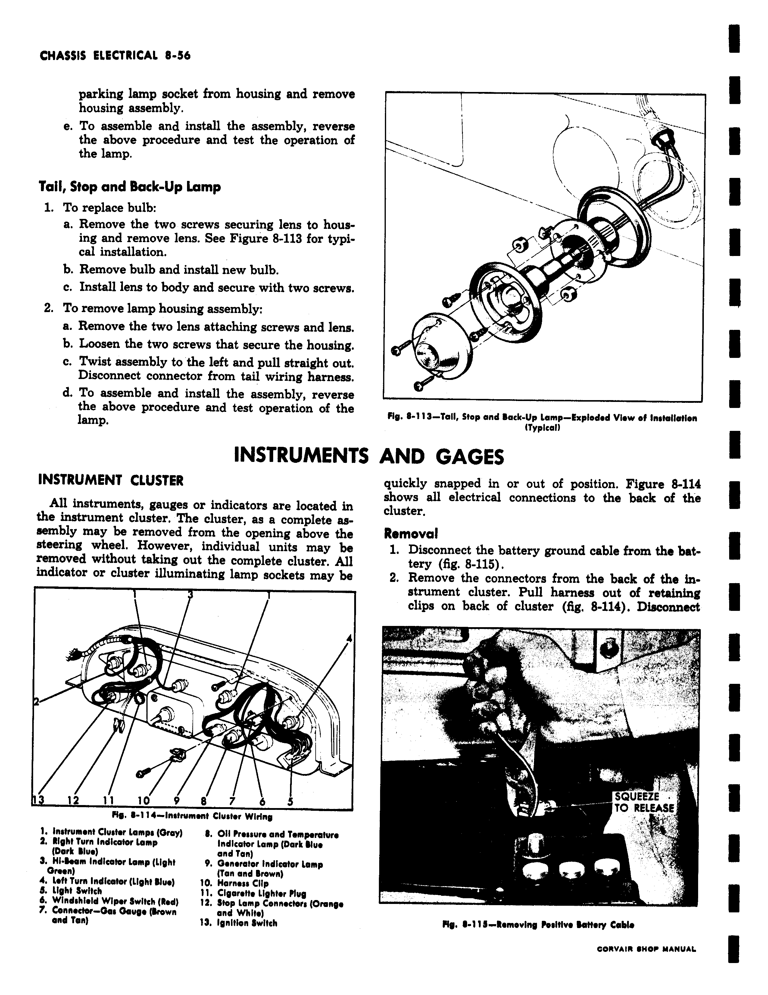
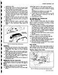
GMA55I5 CLCGIICIVAO o a0 parking lamp socket from housing and remove housing assembly e To assemble and install the assembly reverse the above procedure and test the operation of the lamp Tail Stop and Back Up Lamp 1 To replace bulb a Remove the two screws securing lens to housing and remove lens See Figure 8 113 for typical installation b Remove bulb and install new bulb c Install lens to body and secure with two screws 2 To remove lamp housing assembly a Remove the two lens attaching screws and lens b Loosen the two screws that secure the housing c Twist assembly to the left and pull straight out Disconnect connector from tail wiring harness d To assemble and install the assembly reverse the above procedure and test operation of the lamp INSTRUMENTS INSTRUMENT CLUSTER All instruments gauges or indicators are located in the instrument cluster The cluster as a complete assembly may be removed from the opening above the steering wheel However individual units may be removed without taking out the complete cluster All indicator or cluster illuminating lamp sockets may be 4 v z y 12 il 10 9 8 7 6 S MS 8 1 14 instrument Cluster Wiring 1 Instrument Cluster tamps Gray Oil Pressure and Temperature Z light Turn Indicator Lamp Indicator Lamp Dark Blue Dark Blue and Tan 3 HI Seam Indicator Lamp Light 9 Generator Indicator tamp Green Tan and grown 4 Left Turn Indicator Light Slue 10 Harness Clip a Light Switch 11 Cigarette Lighter Plug 6 Windshield Wiper Switch Red 12 Step Lamp Conneeten Orange 7 Connector Gas Gouge Brown and White and Tan 13 Ignition Switch Fly 113 Toll Stop and Back Up Lamp Exploded View of Installation myplcan AND GAGES quickly snapped in or out of position Figure 8 114 shows all electrical connections to the back of the cluster Removal 1 Disconnect the battery ground cable from the battery fig 8 115 2 Remove the connectors from the back of the instrument cluster Pull harness out of retaining clips on back of cluster fig 8 114 Disconnect SQUEEZE TO RELEASE s Fig 11 i Removing Positive Battery Cable