Jeep Parts Wiki | Ford Parts Wiki
Home | Search | Browse
Prev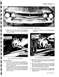
 Next
Next
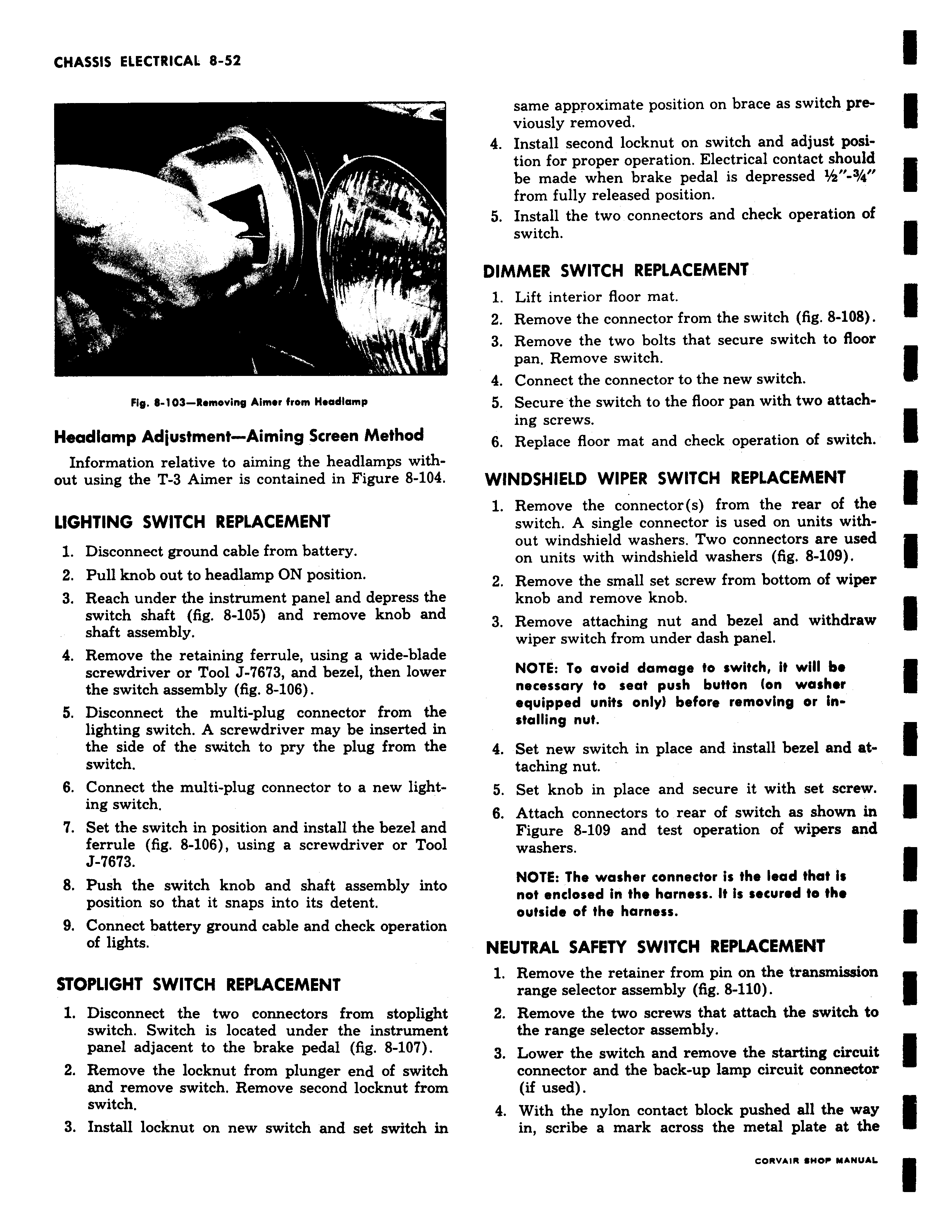
Fig 6 103 Removing Aimer from Headlamp Headlamp Adjustment Aiming Screen Method Information relative to aiming the headlamps without using the T 3 Aimer is contained in Figure 8 104 LIGHTING SWITCH REPLACEMENT 1 Disconnect ground cable from battery 2 Pull knob out to headlamp ON position 3 Reach under the instrument panel and depress the switch shaft fig 8 105 and remove knob and shaft assembly 4 Remove the retaining ferrule using a wide blade screwdriver or Tool J 7673 and bezel then lower the switch assembly fig 8 106 5 Disconnect the multi plug connector from the lighting switch A screwdriver may be inserted in the side of the switch to pry the plug from the switch 6 Connect the multi plug connector to a new lighting switch 7 Set the switch in position and install the bezel and ferrule fig 8 106 using a screwdriver or Tool J 7673 8 Push the switch knob and shaft assembly into position so that it snaps into its detent 9 Connect battery ground cable and check operation of lights STOPLIGHT SWITCH REPLACEMENT 1 Disconnect the two connectors from stoplight switch Switch is located under the instrument panel adjacent to the brake pedal fig 8 107 2 Remove the locknut from plunger end of switch and remove switch Remove second locknut from switch 3 Install locknut on new switch and set switch in same approximate position on brace as switch previously removed 4 Install second locknut on switch and adjust position for proper operation Electrical contact should be made when brake pedal is depressed 3 a from fully released position 5 Install the two connectors and check operation of switch DIMMER SWITCH REPLACEMENT 1 Lift interior floor mat 2 Remove the connector from the switch fig 8 108 3 Remove the two bolts that secure switch to floor pan Remove switch 4 Connect the connector to the new switch 5 Secure the switch to the floor pan with two attaching screws 6 Replace floor mat and check operation of switch WINDSHIELD WIPER SWITCH REPLACEMENT 1 Remove the connector s from the rear of the switch A single connector is used on units without windshield washers Two connectors are used on units with windshield washers fig 8 109 2 Remove the small set screw from bottom of wiper knob and remove knob 3 Remove attaching nut and bezel and withdraw wiper switch from under dash panel NOTE To avoid damage to switch it will be necessary to seat push button on washer equipped units only before removing or installing nut 4 Set new switch in place and install bezel and attaching nut 5 Set knob in place and secure it with set screw 6 Attach connectors to rear of switch as shown in Figure 8 109 and test operation of wipers and washers NOTE The washer connector is the lead that is not enclosed in the harness It is secured to the outside of the harness NEUTRAL SAFETY SWITCH REPLACEMENT 1 Remove the retainer from pin on the transmission range selector assembly fig 8 110 2 Remove the two screws that attach the switch to the range selector assembly 3 Lower the switch and remove the starting circuit connector and the back up lamp circuit connector if used 4 With the nylon contact block pushed all the way in scribe a mark across the metal plate at the enOVWO Y Y YllAl