Jeep Parts Wiki | Ford Parts Wiki
Home | Search | Browse
Prev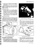
 Next
Next
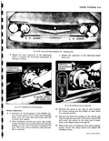
NOTE A quick level check can be made by using the T 3 Safety Aimer as a level Use with a true eight to ten foot two by four as an extension Make sure pads on base of aimer are used Place the board where you expect the wheels to be and take readings as outlined above 6 If either bubble moves outside the black lines of the vial there is too much slant to the floor Try driving the car in at different angles onto the aiming area If bubbles can not be centered follow procedure under How to Compensate for Unlevel Floor NOTE When level portion of floor is obtained mark tire spots on floor so spots can be used next time without calibrating aimer These will be a different set of marks than the ones used for the Chevrolet Passenger Car New marks will be required for the Corvair due to the shorter wheelbase and tread To Compensate for Unlevel Floors If your floor is not level within the limits specified the T 3 Aimer can be calibrated to compensate for the error in the floor Follow this procedure with both aimers 1 Drive the car onto the area for which you wish to compensate the aimers and install the aimers in place on either the No 1 or the No 2 pair of headlamps 2 Loosen knob beneath the aimer arm and move the slider until the bubble is centered 3 Record the numeral in the view window This numeral is to be used only for recalibration 4 Move the slider to a position halfway between this recorded numeral and the numeral 0 in the DOWN window This numeral is used only in recalibration and not for headlamp aiming 5 Recalibrate aimers by turning screw shown in Figure 8 99 until the bubble is centered 6 The T 3 Aimers are now calibrated for the selected area All future aiming must be done in the same area and with the car pointed in the same direction Mark the tire spots on the floor so that future cars Corvairs only can be located in the same position NOTE Due to the difference in wheelbase and tread the Corvair will have different set of marks than the Chevrolet Passenger Car Headlamp Adjustment T 3 Headlamp It is important to note that different aiming specifications are needed for the Corvair This is because headlight beam deflection is downward rather than upward as in the case with front mounted engines Passengers and luggage loaded behind the engine I r i i rwc T t Fig 8 99 Turning Level Adjusting Screw to Calibrate Aimer standard Chevrolet cause upward beam deflection while passenger and luggage loaded in front of the engine cause downward beam deflection 1 Drive vehicle onto selected aiming area Tires should be at recommended pressures and the vehicles should be unloaded no extreme load in front compartment and no passengers 2 Remove headlamp doors 3 Mount the T 3 Aimers on either the No 1 or No 2 pair of headlamps so that the points of the headlamps engage the smooth inner ring of the aimers 4 Secure the aimers to the headlamp units by pressing knob extending out from center of aimer base firmly Rotate the crossarms to approximately horizontal position and pointing toward center of the car 5 With both aimers in place on the same pair of headlamp units knot both ends of the elastic string and fasten using slots provided from the left to the right aimer across the top of the horizontal crossarms fig 8 100 6 Bounce car up and down and roll the vehicle back and forth several times to allow suspension to settle 7 Rotate both aimers so that the points of the crossarms just clear the string Horizontal Adjustment 8 a Turn horizontal aiming screw Figure 8 101 on left hand lamp until the string is positioned over the crossarm centerline Turn the screw clockwise in making the final adjustment to take up play in the headlamp mechanism rnRVAIR SHOP MANUAL