Jeep Parts Wiki | Ford Parts Wiki
Home | Search | Browse
Prev
 Next
Next
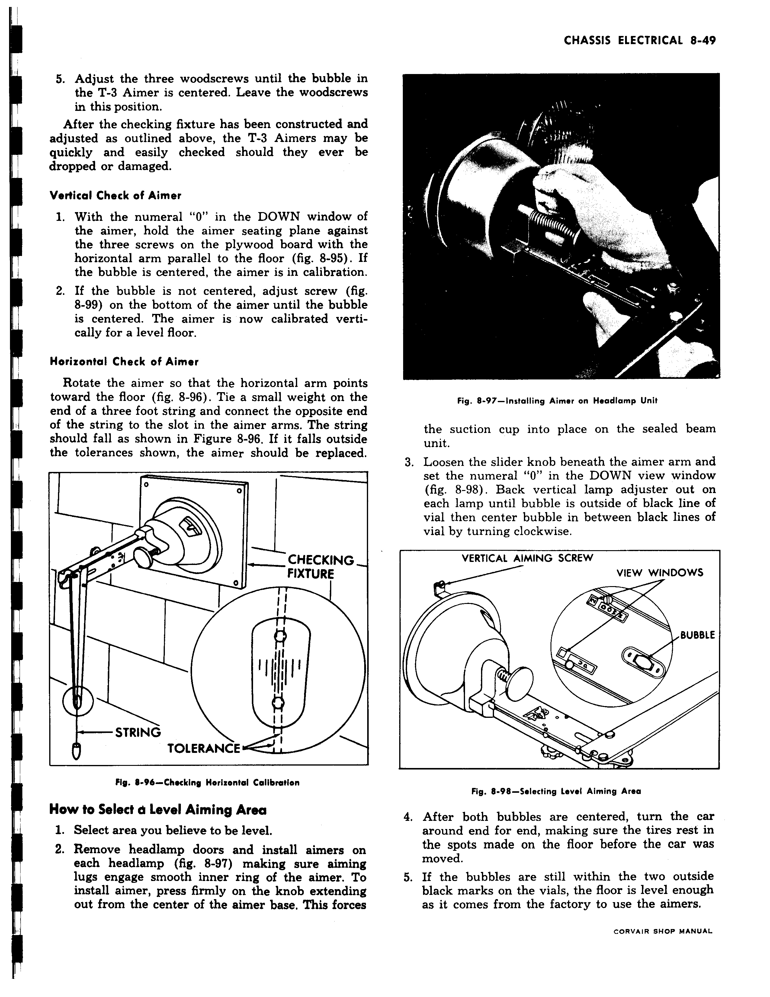
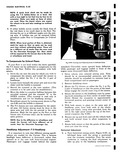
f 5 Adjust the three woodscrews until the bubble in the T 3 Aimer is centered Leave the woodscrews in this position After the checking fixture has been constructed and adjusted as outlined above the T 3 Aimers may be quickly and easily checked should they ever be dropped or damaged Vertical Check of Aimer 1 With the numeral 0 in the DOWN window o the aimer hold the aimer seating plane against the three screws on the plywood board with the horizontal arm parallel to the floor fig 8 95 I the bubble is centered the aimer is in calibration 2 If the bubble is not centered adjust screw fig 8 99 on the bottom of the aimer until the bubble is centered The aimer is now calibrated vertically for a level floor Horizontal Check of Aimer Rotate the aimer so that the horizontal arm points toward the floor fig 8 96 Tie a small weight on the end of a three foot string and connect the opposite end of the string to the slot in the aimer arms The string I should fall as shown in Figure 8 96 If it falls outside the tolerances shown the aimer should be replaced CHECKING FIXTURE 0 v I I pyn STRING TOLERANCE Fly 8 96 Chocking Horizontal Calibration How to Select a Level Aiming Area 1 Select area you believe to be level 2 Remove headlamp doors and install aimers on each headlamp fig 8 97 making sure aiming lugs engage smooth inner ring of the aimer To install aimer press firmly on the knob extending out from the center of the aimer base This forces t l l f lllrr y r s v S v v