Jeep Parts Wiki | Ford Parts Wiki
Home | Search | Browse
Prev
 Next
Next
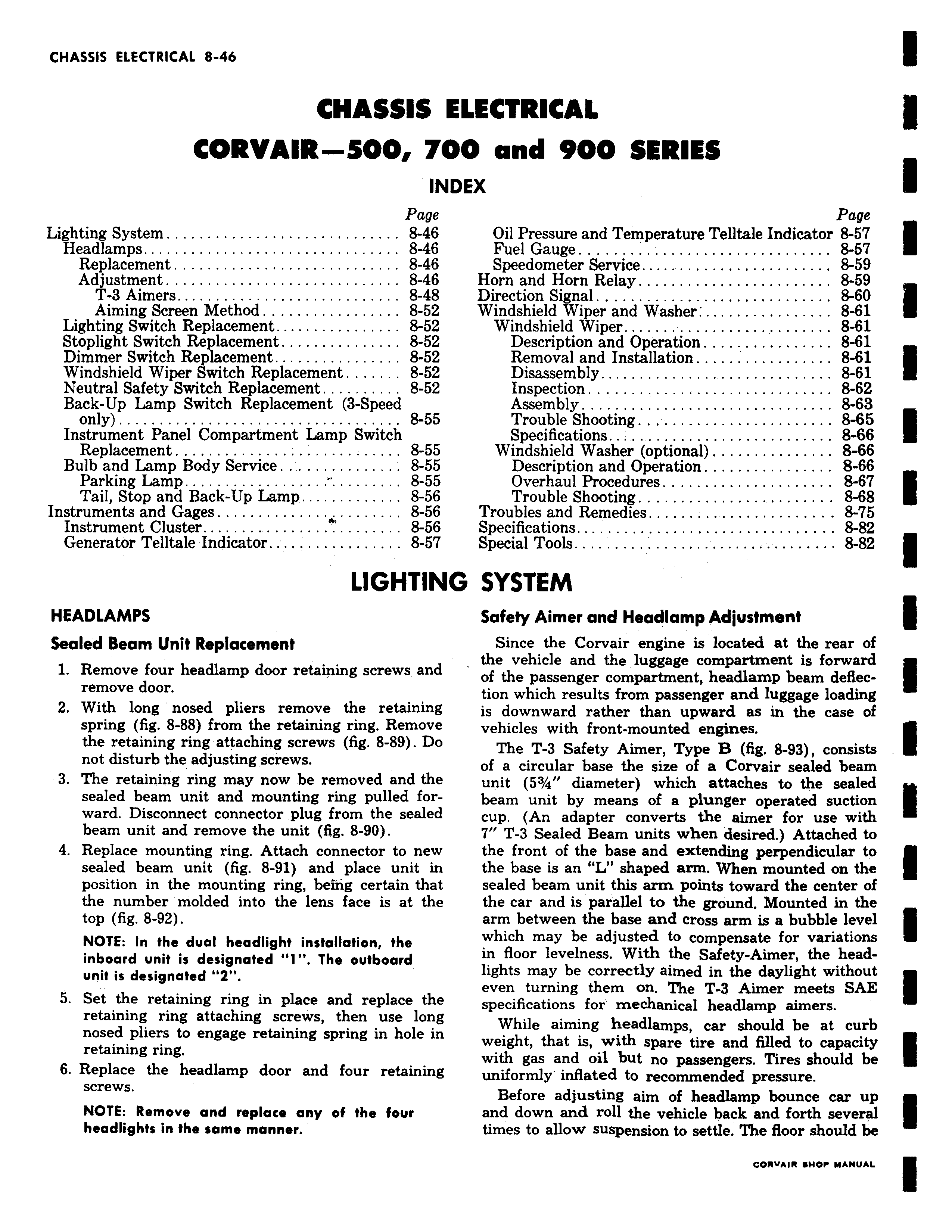
CHASSIS I CORVAIR 500 7C IN Page Lighting System 8 46 Headlamps 8 46 Replacement 8 46 Adjustment 8 46 T 3 Aimers 8 48 Aiming Screen Method 8 52 Lighting Switch Replacement 8 52 Stoplight Switch Replacement 8 52 Dimmer Switch Replacement 8 52 Windshield Wiper Switch Replacement 8 52 Neutral Safety Switch Replacement 8 52 Back Up Lamp Switch Replacement 3 Speed only 8 55 Instrument Panel Compartment Lamp Switch Replacement 8 55 Bulb and Lamp Body Service 8 55 Parking Lamp 8 55 Tail Stop and Back Up Lamp 8 56 Instruments and Gages A 8 56 Instrument Cluster 8 56 Generator Telltale Indicator 8 57 LIGHTINI HEADLAMPS Sealed Beam Unit Replacement 1 Remove four headlamp door retaining screws and remove door 2 With long nosed pliers remove the retaining spring fig 8 88 from the retaining ring Remove the retaining ring attaching screws fig 8 89 Do not disturb the adjusting screws 3 The retaining ring may now be removed and the sealed beam unit and mounting ring pulled forward Disconnect connector plug from the sealed beam unit and remove the unit fig 8 90 4 Replace mounting ring Attach connector to new sealed beam unit fig 8 91 and place unit in position in the mounting ring being certain that the number molded into the lens face is at the top fig 8 92 NOTE In the dual headlight installation the inboard unit is designated I The outboard unit is designated 2 5 Set the retaining ring in place and replace the retaining ring attaching screws then use long nosed pliers to engage retaining spring in hole in retaining ring 6 Replace the headlamp door and four retaining screws NOTE Remove and replace any of the four headlights in the same manner LECTRICAL 10 and 900 SERIES EX Page Oil Pressure and Temperature Telltale Indicator 8 57 Fuel Gauge 8 57 Speedometer Service 8 59 Horn and Horn Relay 8 59 Direction Signal 8 60 Windshield Wiper and Washer 8 61 Windshield Wiper 8 61 Description and Operation 8 61 Removal and Installation 8 61 Disassembly 8 61 Inspection 8 62 Assembly 8 63 Trouble Shooting 8 65 Specifications 8 66 Windshield Washer optional 8 66 Description and Operation 8 66 Overhaul Procedures 8 67 Trouble Shooting 8 68 Troubles and Remedies 8 75 Specifications 8 82 Special Tools 8 82 3 SYSTEM Safety Aimer and Headlamp Adjustment Since the Corvair engine is located at the rear of the vehicle and the luggage compartment is forward of the passenger compartment headlamp beam deflection which results from passenger and luggage loading is downward rather than upward as in the case of vehicles with front mounted engines The T 3 Safety Aimer Type B fig 8 93 consists of a circular base the size of a Corvair sealed beam unit 53 4 diameter which attaches to the sealed beam unit by means of a plunger operated suction cup An adapter converts the simer for use with 7 T 3 Sealed Beam units when desired Attached to the front of the base and extending perpendicular to the base is an L shaped arm When mounted on the sealed beam unit this arm points toward the center of the car and is parallel to the ground Mounted in the arm between the base and cross arm is a bubble level which may be adjusted to compensate for variations in floor levelness With the Safety Aimer the headlights may be correctly aimed in the daylight without even turning them on The T 3 Aimer meets SAE specifications for mechanical headlamp aimers While aiming headlamps car should be at curb weight that is with spare tire and filled to capacity with gas and oil but no passengers Tires should be uniformly inflated to recommended pressure Before adjusting aim of headlamp bounce car up and down and roll the vehicle back and forth several times to allow suspension to settle The floor should be