Jeep Parts Wiki | Ford Parts Wiki
Home | Search | Browse
Prev

 Next
Next
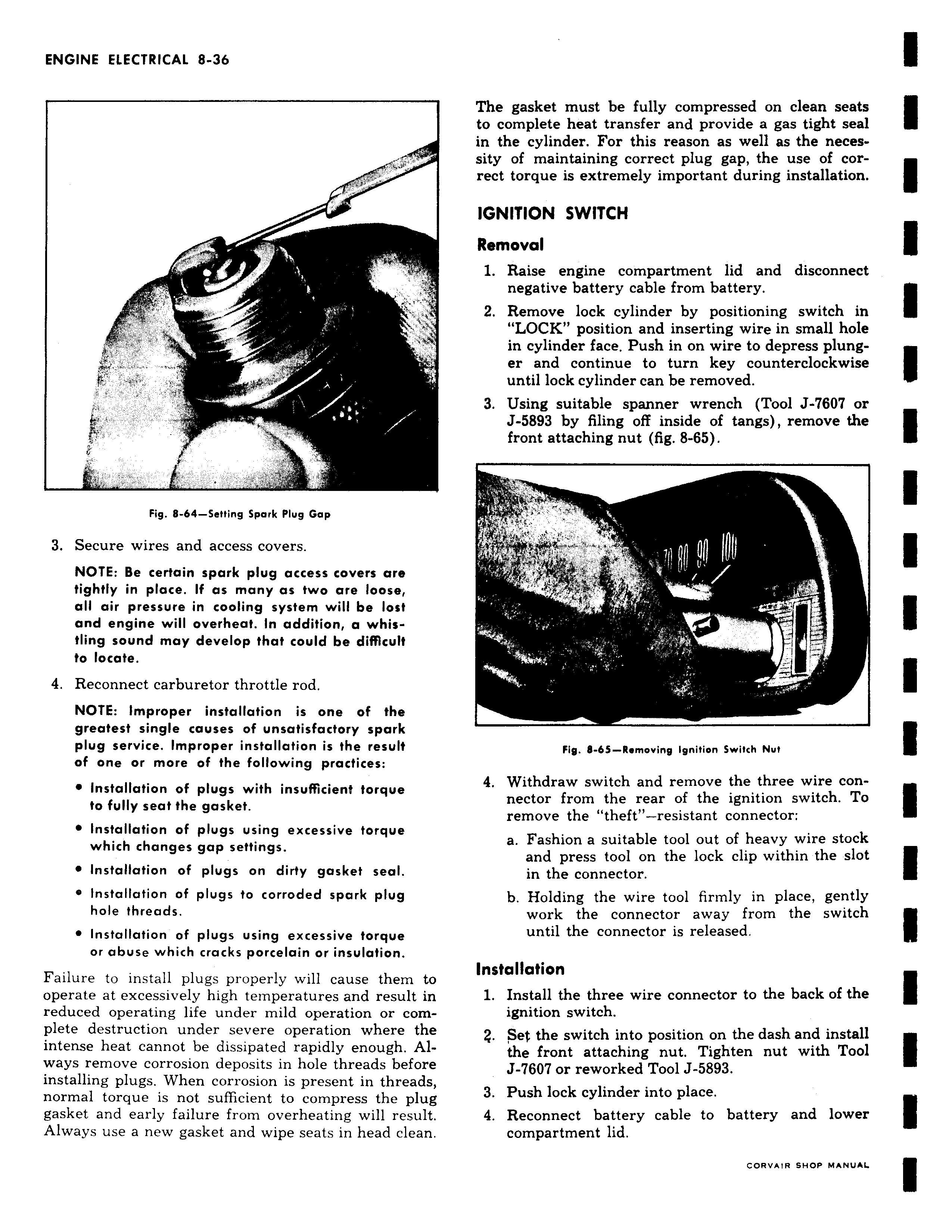
f f M r t L11 Fig 8 64 Setting Spark Plug Gap 3 Secure wires and access covers NOTE Be certain spark plug access covers are tightly in place If as many as two are loose all air pressure in cooling system will be lost and engine will overheat In addition a whistling sound may develop that could be difficult to locate 4 Reconnect carburetor throttle rod NOTE Improper installation is one of the greatest single causes of unsatisfactory spark plug service Improper installation is the result of one or more of the following practices Installation of plugs with insufficient torque to fully seat the gasket Installation of plugs using excessive torque which changes gap settings Installation of plugs on dirty gasket seal Installation of plugs to corroded spark plug hole threads Installation of plugs using excessive torque or abuse which cracks porcelain or insulation Failure to install plugs properly will cause them to operate at excessively high temperatures and result in reduced operating life under mild operation or complete destruction under severe operation where the intense heat cannot be dissipated rapidly enough Always remove corrosion deposits in hole threads before installing plugs When corrosion is present in threads normal torque is not sufficient to compress the plug gasket and early failure from overheating will result Always use a new gasket and wipe seats in head clean The gasket must be fully compressed on clean seats to complete heat transfer and provide a gas tight seal in the cylinder For this reason as well as the necessity of maintaining correct plug gap the use of correct torque is extremely important during installation IGNITION SWITCH Removal 1 Raise engine compartment lid and disconnect negative battery cable from battery 2 Remove lock cylinder by positioning switch in LOCK position and inserting wire in small hole in cylinder face Push in on wire to depress plung er and continue to turn key counterclockwise until lock cylinder can be removed 3 Using suitable spanner wrench Tool J 7607 or J 5893 by filing off inside of tangs remove the front attaching nut fig 8 65 vt rx a Fig 8 65 Removing Ignition Switch Nut 4 Withdraw switch and remove the three wire connector from the rear of the ignition switch To remove the theft resistant connector a Fashion a suitable tool out of heavy wire stock and press tool on the lock clip within the slot in the connector b Holding the wire tool firmly in place gently work the connector away from the switch until the connector is released Installation 1 Install the three wire connector to the back of the ignition switch Z Set the switch into position on the dash and install the front attaching nut Tighten nut with Tool J 7607 or reworked Tool J 5893 3 Push lock cylinder into place 4 Reconnect battery cable to battery and lower compartment lid

 Next
Next