Jeep Parts Wiki | Ford Parts Wiki
Home | Search | Browse | Marketplace | Messages | FAQ | Guest
Prev

 Next
Next
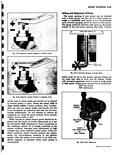
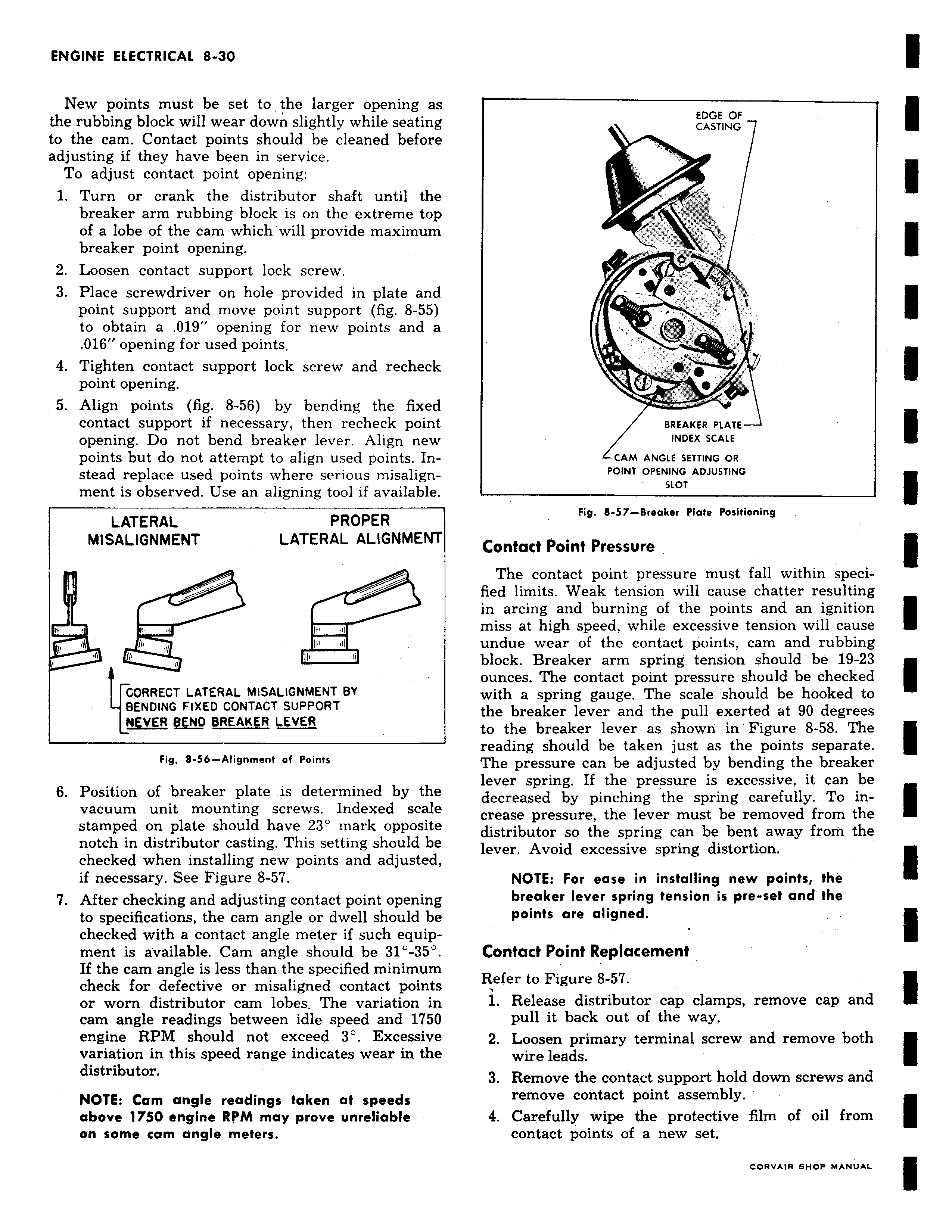
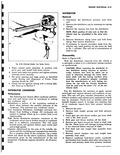
New points must be set to the larger opening as the rubbing block will wear down slightly while seating to the cam Contact points should be cleaned before adjusting if they have been in service To adjust contact point opening 1 Turn or crank the distributor shaft until the breaker arm rubbing block is on the extreme top of a lobe of the cam which will provide maximum breaker point opening 2 Loosen contact support lock screw 3 Place screwdriver on hole provided in plate and point support and move point support fig 8 55 to obtain a 019 opening for new points and a 016 opening for used points 4 Tighten contact support lock screw and recheck point opening 5 Align points fig 8 56 by bending the fixed contact support if necessary then recheck point opening Do not bend breaker lever Align new points but do not attempt to align used points Instead replace used points where serious misalignment is observed Use an aligning tool if available LATERAL PROPER F MISALIGNMENT LATERAL ALIGNMENT i w a n p n n CORRECT LATERAL MISALIGNMENT BY BENDING FIXED CONTACT SUPPORT NEVER SEND BREAKER LEVER Fig 8 56 Alignment of Points 6 Position of breaker plate is determined by the vacuum unit mounting screws Indexed scale stamped on plate should have 23 mark opposite notch in distributor casting This setting should be checked when installing new points and adjusted if necessary See Figure 8 57 7 After checking and adjusting contact point opening to specifications the cam angle or dwell should be checked with a contact angle meter if such equip ment is available Cam angle should be 31 35 If the cam angle is less than the specified minimum check for defective or misaligned contact points or worn distributor cam lobes The variation in cam angle readings between idle speed and 1750 engine RPM should not exceed 3 Excessive variation in this speed range indicates wear in the distributor NOTE Cam angle readings taken at speeds above 1750 engine RPM may prove unreliable on some cam angle meters EDGE OF CASTING T 0 e 1 BREAKER PLATE INDEX SCALE CAM ANGLE SETTING OR POINT OPENING ADJUSTING SLOT Fig 8 57 Breaker Plate Positioning Contact Point Pressure The contact point pressure must fall within specified limits Weak tension will cause chatter resulting in arcing and burning of the points and an ignition miss at high speed while excessive tension will cause undue wear of the contact points cam and rubbing block Breaker arm spring tension should be 19 23 ounces The contact point pressure should be checked with a spring gauge The scale should be hooked to the breaker lever and the pull exerted at 90 degrees to the breaker lever as shown in Figure 8 58 The reading should be taken just as the points separate The pressure can be adjusted by bending the breaker lever spring If the pressure is excessive it can be decreased by pinching the spring carefully To increase pressure the lever must be removed from the distributor so the spring can be bent away from the lever Avoid excessive spring distortion NOTE For ease in installing new points the breaker lever spring tension is pre set and the points are aligned Contact Point Replacement Refer to Figure 8 57 1 Release distributor cap clamps remove cap and pull it back out of the way 2 Loosen primary terminal screw and remove both wire leads 3 Remove the contact support hold down screws and remove contact point assembly 4 Carefully wipe the protective film of oil from contact points of a new set

 Next
Next