Jeep Parts Wiki | Ford Parts Wiki
Home | Search | Browse | Marketplace | Messages | FAQ | Guest
Prev
 Next
Next
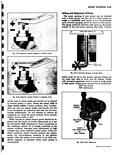
Step No Operation Speciflca 8 If these checks fail to find cause of trouble remove distributor coil and resistance wire from engine and check to specifications Also check wiring harness SERVICING OF UNI1 DISTRIBUTOR CONTACT POINTS Criteria for Replacing Points Examine the distributor points Dirty points should be cleaned with a clean point file Normal point condition is an overall grey color If a test instrument for checking resistance is available check the point resistance The criteria for point quality should be a combination of visual inspection and a resistance or voltage drop check If the points are badly worn pitted or misaligned replacement is recommended If with the points closed and the ignition switch in the ON position there is less than a 0 125 volt drop across the points the points may be considered satisfactory for further use This check may be made with a sensitive voltmeter or one of the various point resistance meters available for this purpose Abnormal Point Wear Under normal operating conditions distributor contact points will provide many thousands of miles of service Points which have undergone several thousand miles of operation will have a rough surface but this should not be interpreted as meaning that the points are worn out If the roughness between the points matches so that a large contact area is maintained the points will continue to provide satisfactory service until most of the tungsten is worn off However if the points burn or pit they will soon become unsatisfactory for further operation Not only must they be replaced but the ignition system and engine must be checked to determine the cause of the trouble so it can be eliminated Unless the condition causing the point burning or pitting is corrected the new points will provide no better service than the old points Burning of Points Contact point burning will result from high voltage presence of oil or other foreign material defective condenser and improper point adjustment High voltage causes an excessively high current flow through the contact points which burns them rapidly High voltage can result from an improperly adjusted or inoperative voltage regulator tion Possible Trouble S OFF THE VEHICLE Oil or crankcase vapors which work up into the distributor and deposit on the point surfaces will cause them to burn rapidly This is easy to detect since the oil produces a smudgy line under the contact points Clogged engine breather pipes permit crankcase pressure to force oil or vapors up into the distributor Over oiling the distributor will also produce the condition If the contact point opening is too small cam angle too large the points will be closed too large a part of the total operating time Average current flow through the points will be too high so the points will burn rapidly and arcing will occur between the points resulting in low secondary voltage and engine miss High series resistance in the condenser circuit will prevent normal condenser action so the contact points will burn rapidly This resistance may be caused by a loose condenser mounting or lead connection or by poor connections inside the condenser See Distributor Condenser in this section for a discussion of condenser testing Pitting of Points Contact point pitting results from an out of balance condition in the ignition system which causes transfer of tungsten from one point to the other so that a tip builds up on one point while a pit forms in the other figs 8 52 and 8 53 The direction in which the tungsten transfers can be used as a basis for analysis and correction of pitting For instance if the material transfers from the negative to the positive point fig 8 52 one or more of these corrections may be made increase condenser capacity shorten condenser lead separate distributor to coil low and high tension leads move these leads closer to ground If the material transfers from the positive to the negative point fig 8 53 reduce condenser capacity move distributor to coil leads closer together move these leads away from ground or lengthen condenser lead Cleaning of Points Dirty contact points should be dressed with a few strokes of a clean fine cut contact file The file should