Jeep Parts Wiki | Ford Parts Wiki
Home | Search | Browse
Prev
 Next
Next
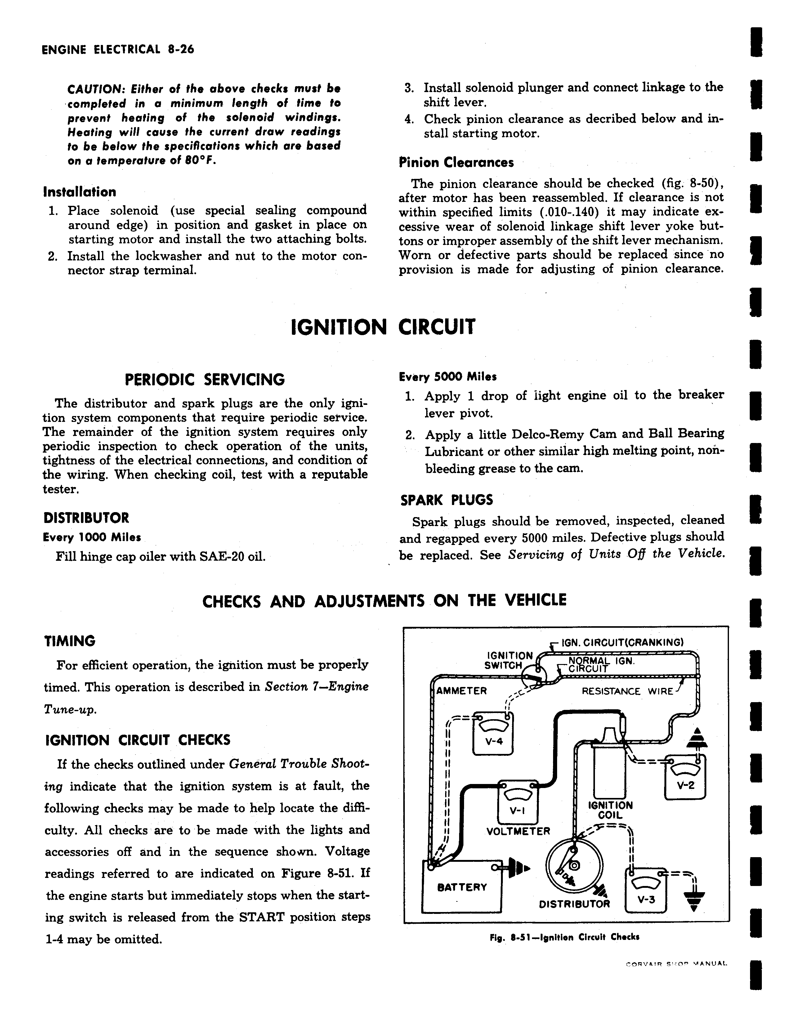
CAUTION Either of the above checks must be completed in a minimum length of time to prevent heating of the solenoid windings Heating will cause the current draw readings to be below the specifications which are based on a temperature of 80 F Installation 1 Place solenoid use special sealing compound around edge in position and gasket in place on starting motor and install the two attaching bolts 2 Install the lockwasher and nut to the motor connector strap terminal IGNITIOI PERIODIC SERVICING The distributor and spark plugs are the only ignition system components that require periodic service The remainder of the ignition system requires only periodic inspection to check operation of the units tightness of the electrical connections and condition of the wiring When checking coil test with a reputable tester DISTRIBUTOR Every 1000 Miles Fill hinge cap oiler with SAE 20 oil CHECKS AND ADJUSTI TIMING For efficient operation the ignition must be properly timed This operation is described in Section 7 Engine Tune up IGNITION CIRCUIT CHECKS If the checks outlined under General Trouble Shooting indicate that the ignition system is at fault the following checks may be made to help locate the difficulty All checks are to be made with the lights and accessories off and in the sequence shown Voltage readings referred to are indicated on Figure 8 51 If the engine starts but immediately stops when the starting switch is released from the START position steps 1 4 may be omitted 3 Install solenoid plunger and connect linkage to the shift lever 4 Check pinion clearance as decribed below and install starting motor Pinion Clearances The pinion clearance should be checked fig 8 50 after motor has been reassembled If clearance is not within specified limits 010 140 it may indicate excessive wear of solenoid linkage shift lever yoke buttons or improper assembly of the shift lever mechanism Worn or defective parts should be replaced since no provision is made for adjusting of pinion clearance 4 CIRCUIT Every 5000 Miles 1 Apply 1 drop of light engine oil to the breaker lever pivot 2 Apply a little Delco Remy Cam and Ball Bearing Lubricant or other similar high melting point nonbleeding grease to the cam SPARK PLUGS Spark plugs should be removed inspected cleaned and regapped every 5000 miles Defective plugs should be replaced See Servicing of Units Of the Vehicle VIENTS ON THE VEHICLE IGN CIRCUIT CRANKING IGNITION NpRMAL IGN SWITCH CIRCUIT AMMETER L RESISTANCE WIREJ II il V q 11 II ii Q v 2 11 IGNITION II V I COIL VOLTMETER k n 0 11 vBATTERY DISTRIBUTOR V 3 Fig 8 51 Ignition Circuit Checks ti