Jeep Parts Wiki | Ford Parts Wiki
Home | Search | Browse | Marketplace | Messages | FAQ | Guest
Prev
 Next
Next
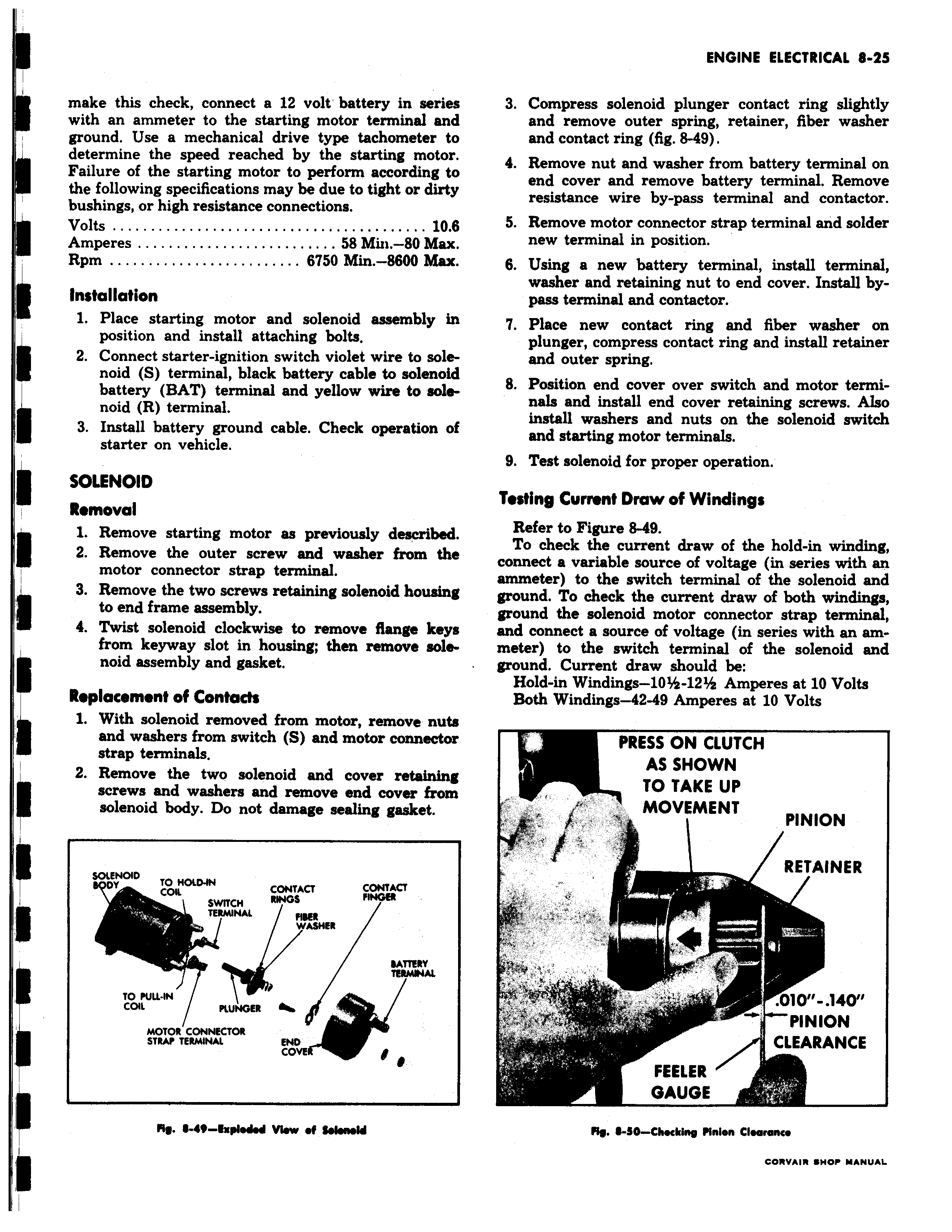
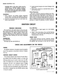
make this check connect a 12 volt battery in serie with an ammeter to the starting motor terminal ani ground Use a mechanical drive type tachometer b I determine the speed reached by the starting moto Failure of the starting motor to perform according ti the following specifications may be due to tight or dirt bushings or high resistance connections Volts 10 1 Amperes 58 Min 80 Max Rpm 6750 Min 8600 Max Installation L 1 Place starting motor and solenoid assembly v position and install attaching bolts 2 Connect starter ignition switch violet wire to sole noid S terminal black battery cable to solenoit battery BAT terminal and yellow wire to sole noid R terminal 3 Install battery ground cable Check operation o starter on vehicle I SOLENOID Removal 1 Remove starting motor as previously described 2 Remove the outer screw and washer from th4 motor connector strap terminal 3 Remove the two screws retaining solenoid housini to end frame assembly 4 Twist solenoid clockwise to remove flange key from keyway slot in housing then remove sole noid assembly and gasket Replacement of Contact 1 With solenoid removed from motor remove nut and washers from switch S and motor connecta strap terminals 2 Remove the two solenoid and cover rettaininj screws and washers and remove end cover fron solenoid body Do not damage sealing gasket SOLENOID TO MOIDaN COIL CONTACT CONTACT SWITCH RINGS TERMINAL DY MINAI WASHER M To PULL IN TERMINAL Cat PLUNGER MOTOR CONNECTOR STRAP TERMINAL END covE I 14 N Exploded View of fNendd s 3 Compress solenoid plunger contact ring slightly i and remove outer spring retainer fiber washer and contact ring fig 8 49 4 Remove nut and washer from battery terminal on end cover and remove battery terminal Remove resistance wire by pass terminal and contactor 5 Remove motor connector strap terminal and solder new terminal in position 6 Using a new battery terminal install terminal washer and retaining nut to end cover Install bypass terminal and contaMor i 7 Place new contact ring and fiber washer on plunger compress contact ring and install retainer and outer spring i 8 Position end cover over switch and motor terminals and install end cover retaining screws Also E install washers and nuts on the solenoid switch and starting motor terminals 9 Test solenoid for proper operation Testing Current Draw of Windings Refer to Figure 8 49 To check the current draw of the hold in winding connect a variable source of voltage in series with an ammeter to the switch terminal of the solenoid and t ground To check the current draw of both windings ground the solenoid motor connector strap terminal s and connect a source of voltage in series with an ammeter to the switch terminal of the solenoid and ground Current draw should be Hold in Windings 10 12 Amperes at 10 Volts Both Windings 42 49 Amperes at 10 Volts PRESS ON CLUTCH AS SHOWN TO TAKE UP MOVEMENT PINION RETAINER n4 4 010 140 PINION CLEARANCE Fs FEELER 3 GAUGE M R S0 Checking Pinion Clearance