Jeep Parts Wiki | Ford Parts Wiki
Home | Search | Browse | Marketplace | Messages | FAQ | Guest
Prev

 Next
Next
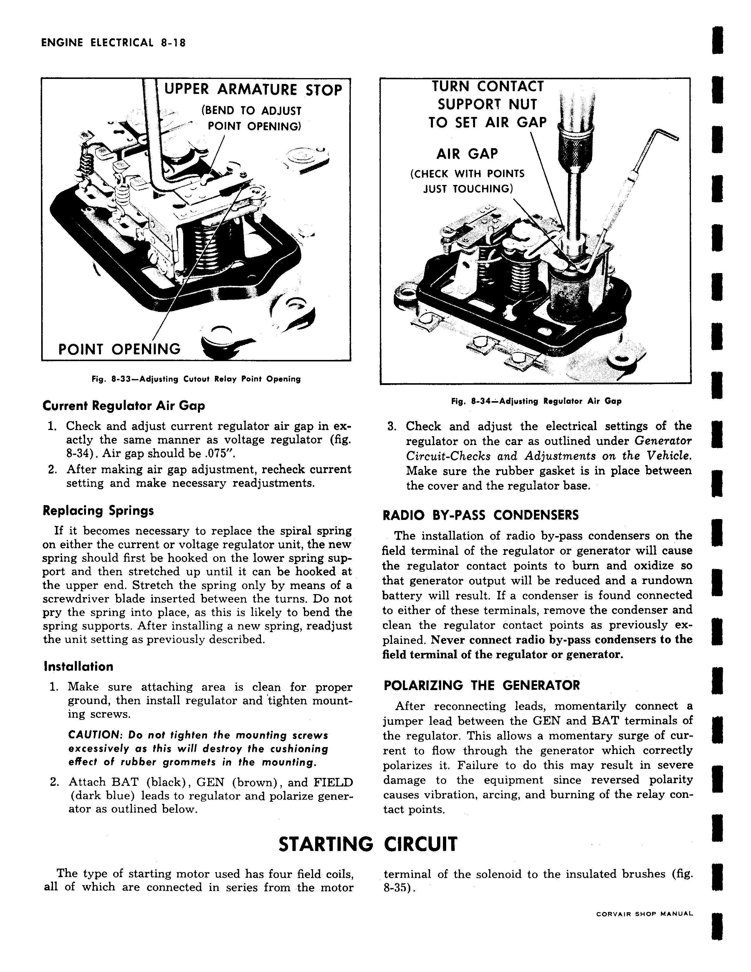
UPPE R ARMATURE STOP EBEND TO ADJUST P 11 NT OPENING POINT OPENING Fig 8 33 Adjusting Cutout Relay Point Opening Current Regulator Air Gap 1 Check and adjust current regulator air gap in exactly the same manner as voltage regulator fig 8 34 Air gap should be 075 1 After making air pip adjustment recheck current setting and make necessary readjustments Replacing Springs If it becomes necessary to replace the spiral spring on either the current or voltage regulator unit the new spring should first be hooked on the lower spring support and then stretched up until it can be hooked at the upper end Stretch the spring only by means of a screwdriver blade inserted between the turns Do not pry the spring into place as this is likely to bend the spring supports After KsWH g a new spring readjust the unit setting as previously described Installation 1 Make sure attaching area is clean for proper ground then install regulator andtighten mounting screws CAUTION Do not tighten the mounting screws excessively as this will destroy the cushioning effect of rubber grommets in the mounting 2 Attach BAT black GEN brown and FIELD dark blue leads to regulator and polarize generator as outlined below STARTIN The type of starting motor used has four field coils all of which are connected in series from the motor TURN CONTACT SUPPORT NUT TO SET AIR GAP AIR GAP CHECK WITH POINTS JUST TOUCHING AO 1 J Fig 8 34 Adjusting Regulator Air Gap 3 Check and adjust the electrical settings of the regulator on the car as outlined under Generator Circuit Checks and Adjustments on the Vehicle Make sure the rubber gasket is in place between the cover and the regulator base RADIO BY PASS CONDENSERS The installation of radio by pass condensers on the field terminal of the regulator or generator will cause the regulator contact points to burn and oxidize so that generator output will be reduced and a rundown battery will result If a condenser is found connectedto either of these terminals remove the condenser and dean the regulator contact points as previously explained Never connect radio by pass condensers to the field terminal of the regulator or generator POLARIZING THE GENERATOR After reconnecting leads momentarily connect a jumper lead between the GEN and BAT terminals of the regulator This allows a momentary surge of current to flow through the generator which correctly polarizes it Failure to do this may result in severe damage to the equipment since reversed polarity causes vibration arcing and burning of the relay contact points G CIRCUIT terminal of the solenoid to the insulated brushes fig 8 35 CORVAIR SHOP MANUAL

 Next
Next