Jeep Parts Wiki | Ford Parts Wiki
Home | Search | Browse | Marketplace | Messages | FAQ | Guest
Prev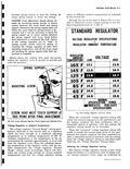
 Next
Next
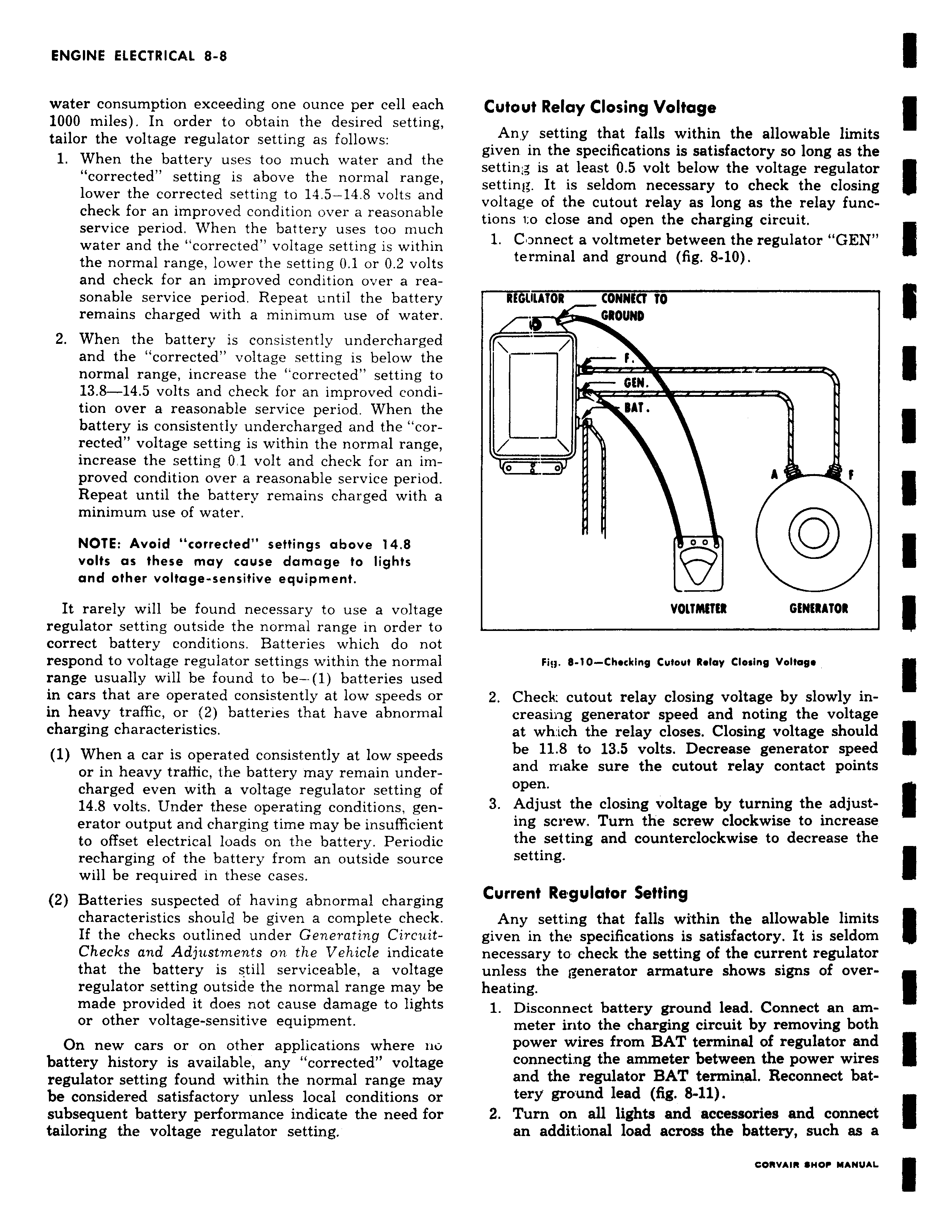
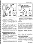
water consumption exceeding one ounce per cell each 1000 miles In order to obtain the desired setting tailor the voltage regulator setting as follows 1 When the battery uses too much water and the corrected setting is above the normal range lower the corrected setting to 14 5 14 8 volts and check for an improved condition over a reasonable service period When the battery uses too much water and the corrected voltage setting is within the normal range lower the setting 0 1 or 0 2 volts and check for an improved condition over a reasonable service period Repeat until the battery remains charged with a minimum use of water 2 When the battery is consistently undercharged and the corrected voltage setting is below the normal range increase the corrected setting to 13 8 14 5 volts and check for an improved condition over a reasonable service period When the battery is consistently undercharged and the corrected voltage setting is within the normal range increase the setting 0 1 volt and check for an improved condition over a reasonable service period Repeat until the battery remains charged with a minimum use of water NOTE Avoid corrected settings above 14 8 volts as these may cause damage to lights and other voltage sensitive equipment It rarely will be found necessary to use a voltage regulator setting outside the normal range in order to correct battery conditions Batteries which do not respond to voltage regulator settings within the normal range usually will be found to be 1 batteries used in cars that are operated consistently at low speeds or in heavy traffic or 2 batteries that have abnormal charging characteristics 1 When a car is operated consistently at low speeds or in heavy trafiic the battery may remain undercharged even with a voltage regulator setting of 14 8 volts Under these operating conditions generator output and charging time may be insufficient to offset electrical loads on the battery Periodic recharging of the battery from an outside source will be required in these cases 2 Batteries suspected of having abnormal charging characteristics should be given a complete check If the checks outlined under Generating Circuit Checks and Adjustments on the Vehicle indicate that the battery is still serviceable a voltage regulator setting outside the normal range may be made provided it does not cause damage to lights or other voltage sensitive equipment On new cars or on other applications where no battery history is available any corrected voltage regulator setting found within the normal range may be considered satisfactory unless local conditions or subsequent battery performance indicate the need for tailoring the voltage regulator setting Cutout Relay Closing Voltage Any setting that falls within the allowable limits given in the specifications is satisfactory so long as the settin is at least 0 5 volt below the voltage regulator setting It is seldom necessary to check the closing voltage of the cutout relay as long as the relay functions to close and open the charging circuit 1 Connect a voltmeter between the regulator GEN terminal and ground fig 8 10 REGULATOR CONNECT TO GROUND f GEN PIK RAT o o A f 0 0 VOLTMETER GENERATOR Fiy 8 10 Chscking Cutout Relay Closing Voltage 2 Check cutout relay closing voltage by slowly increasing generator speed and noting the voltage at wh ich the relay closes Closing voltage should be 11 8 to 13 5 volts Decrease generator speed and make sure the cutout relay contact points open 3 Adjust the closing voltage by turning the adjusting screw Turn the screw clockwise to increase the setting and counterclockwise to decrease the setting Current Regulator Setting Any setting that falls within the allowable limits given in the specifications is satisfactory It is seldom necessary to check the setting of the current regulator unless the generator armature shows signs of overheating 1 Disconnect battery ground lead Connect an ammeter into the charging circuit by removing both power wires from BAT terminal of regulator and connecting the ammeter between the power wires and the regulator BAT terminal Reconnect battery ground lead fig 8 11 2 Turn on all lights and accessories and connect an additional load across the battery such as a