Jeep Parts Wiki | Ford Parts Wiki
Home | Search | Browse
Prev
 Next
Next
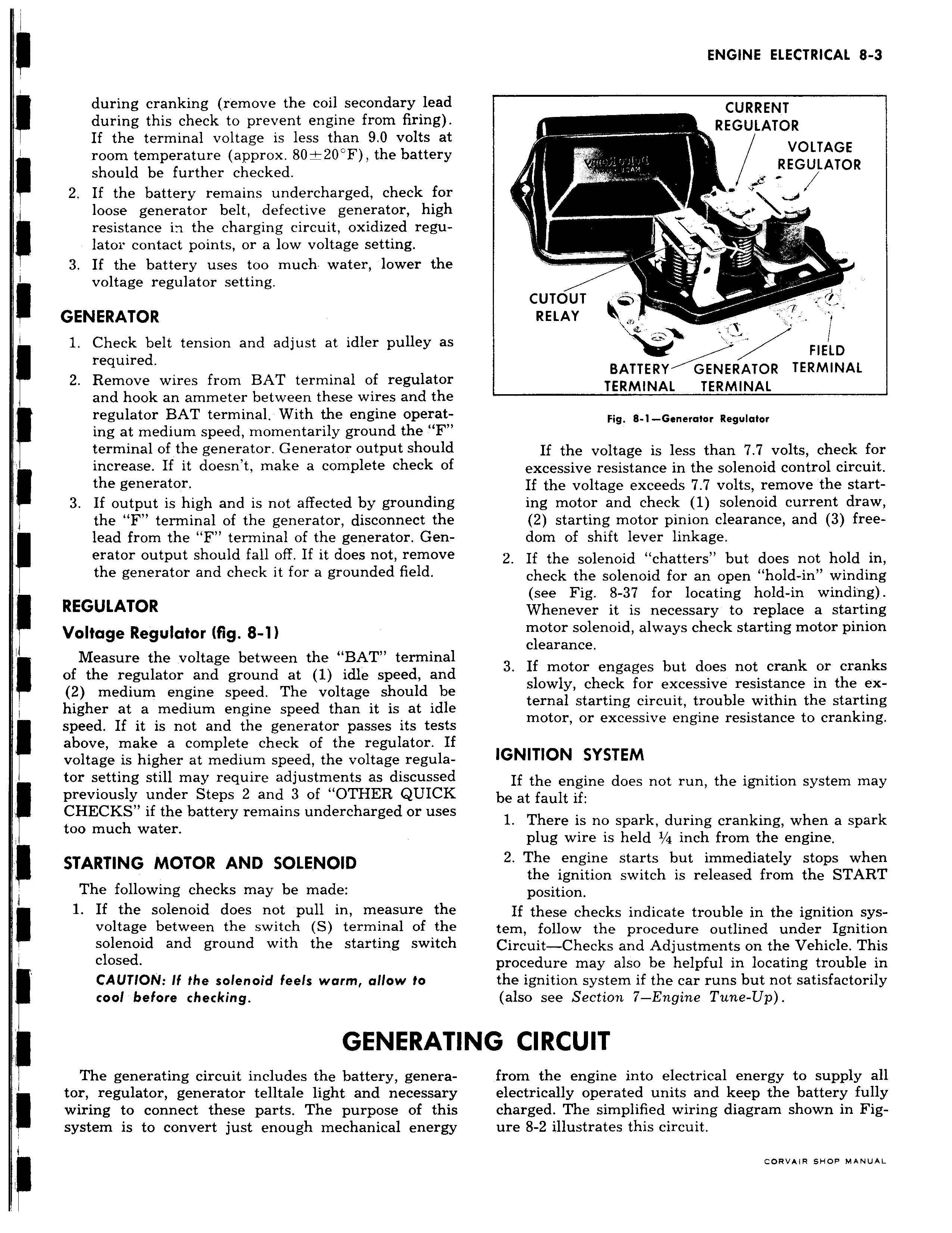
during cranking remove the coil secondary lead during this check to prevent engine from firing If the terminal voltage is less than 9 0 volts at room temperature approx 80 20 F the battery should be further checked 2 If the battery remains undercharged check for loose generator belt defective generator high resistance in the charging circuit oxidized regulator contact points or a low voltage setting 3 If the battery uses too much water lower the voltage regulator setting GENERATOR I 1 Check belt tension and adjust at idler pulley as required 2 Remove wires from BAT terminal of regulator and hook an ammeter between these wires and the regulator BAT terminal With the engine operat ing at medium speed momentarily ground the F terminal of the generator Generator output should increase If it doesn t make a complete check of the generator 3 If output is high and is not affected by grounding the F terminal of the generator disconnect the I lead from the F terminal of the generator Generator output should fall off If it does not remove the generator and check it for a grounded field REGULATOR Voltage Regulator fig 8 1 Measure the voltage between the BAT terminal of the regulator and ground at 1 idle speed and 2 medium engine speed The voltage should be higher at a medium engine speed than it is at idle speed If it is not and the generator passes its test above make a complete check of the regulator I1 voltage is higher at medium speed the voltage regulator setting still may require adjustments as discusseo previously under Steps 2 and 3 of OTHER QUICK CHECKS if the battery remains undercharged or use too much water STARTING MOTOR AND SOLENOID The following checks may be made 1 If the solenoid does not pull in measure the voltage between the switch S terminal of the solenoid and ground with the starting switcl closed CAUTION If the solenoid feels warm allow to cool before checking GENERAT The generating circuit includes the battery genera I tor regulator generator telltale light and necessar3 wiring to connect these parts The purpose of thi system is to convert just enough mechanical energ3 f CURRENT REGULATOR VOLTAGE REGULATOR l i CUTOUT RELAY L FIELD BATTERY GENERATOR TERMINAL TERMINAL TERMINAL Fig 8 1 Generator Regulator If the voltage is less than 7 7 volts check for excessive resistance in the solenoid control circuit If the voltage exceeds 7 7 volts remove the starting motor and check 1 solenoid current draw 2 starting motor pinion clearance and 3 freedom of shift lever linkage 2 If the solenoid chatters but does not hold in check the solenoid for an open hold in winding see Fig 8 37 for locating hold in winding Whenever it is necessary to replace a starting motor solenoid always check starting motor pinion clearance 3 If motor engages but does not crank or cranks slowly check for excessive resistance in the external starting circuit trouble within the starting motor or excessive engine resistance to cranking IGNITION SYSTEM If the engine does not run the ignition system may be at fault if 1 There is no spark during cranking when a spark plug wire is held i 4 inch from the engine 2 The engine starts but immediately stops when the ignition switch is released from the START position If these checks indicate trouble in the ignition system follow the procedure outlined under Ignition Circuit Checks and Adjustments on the Vehicle This procedure may also be helpful in locating trouble in the ignition system if the car runs but not satisfactorily also see Section 7 Engine Tune Up ING CIRCUIT from the engine into electrical energy to supply all electrically operated units and keep the battery fully charged The simplified wiring diagram shown in Figure 8 2 illustrates this circuit rnovevo cwna uanweo