Jeep Parts Wiki | Ford Parts Wiki
Home | Search | Browse
Prev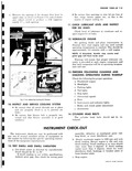
 Next
Next
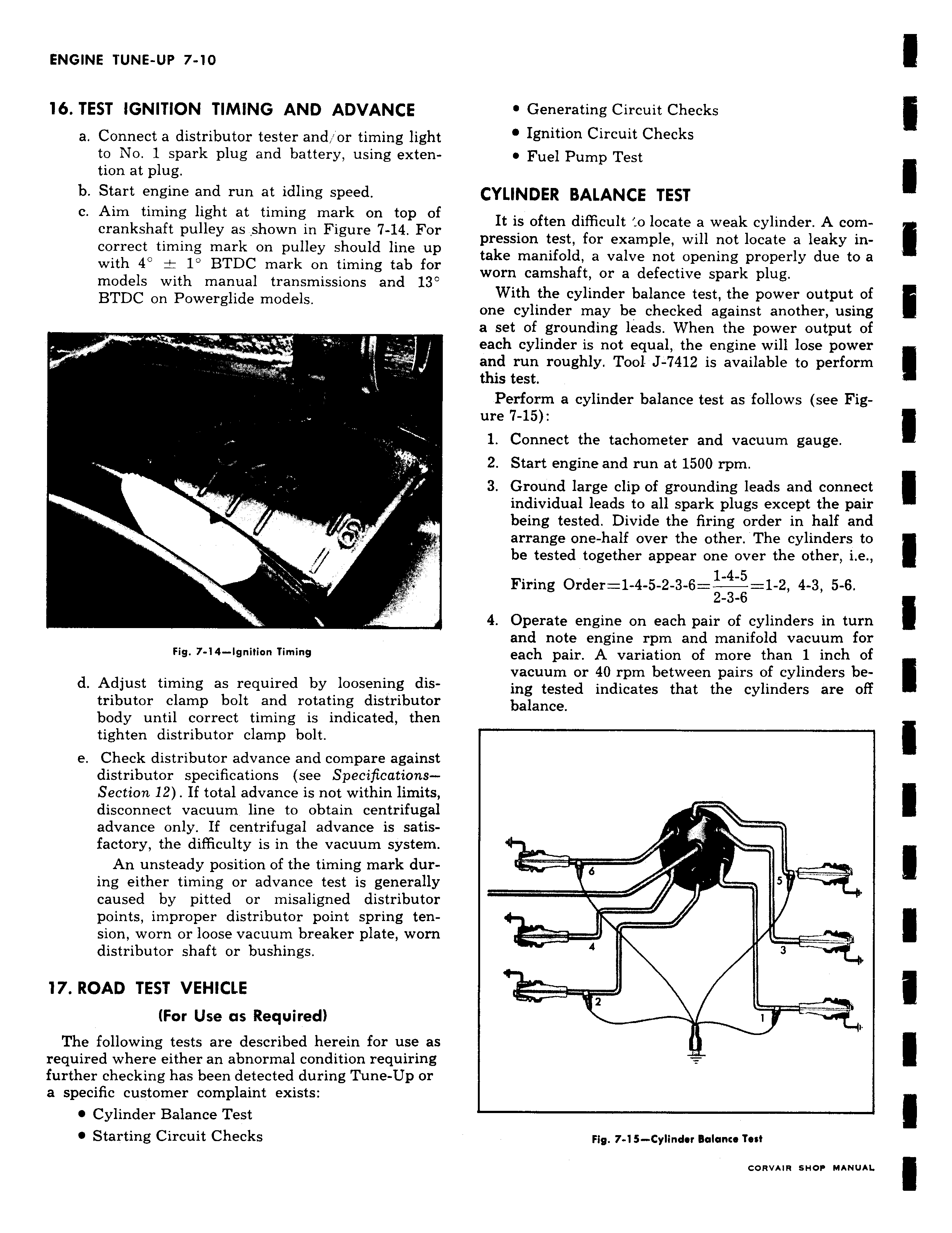
16 TEST IGNITION TIMING AND ADVANCE a Connect a distributor tester and or timing light to No 1 spark plug and battery using extention at plug b Start engine and run at idling speed c Aim timing light at timing mark on top of crankshaft pulley as shown in Figure 7 14 For correct timing mark on pulley should line up with 4 1 BTDC mark on timing tab for models with manual transmissions and 13 BTDC on Powerglide models a Fig 7 14 Ignition Timing d Adjust timing as required by loosening distributor clamp bolt and rotating distributor body until correct timing is indicated then tighten distributor clamp bolt e Check distributor advance and compare against distributor specifications see SpecificationsSection 12 If total advance is not within limits disconnect vacuum line to obtain centrifugal advance only If centrifugal advance is satisfactory the difficulty is in the vacuum system An unsteady position of the timing mark during either timing or advance test is generally caused by pitted or misaligned distributor points improper distributor point spring tension worn or loose vacuum breaker plate worn distributor shaft or bushings 17 ROAD TEST VEHICLE For Use as Required The following tests are described herein for use as required where either an abnormal condition requiring further checking has been detected during Tune Up or a specific customer complaint exists Cylinder Balance Test Starting Circuit Checks Generating Circuit Checks Ignition Circuit Checks Fuel Pump Test CYLINDER BALANCE TEST It is often difficult o locate a weak cylinder A compression test for example will not locate a leaky intake manifold a valve not opening properly due to a worn camshaft or a defective spark plug With the cylinder balance test the power output of one cylinder may be checked against another using a set of grounding leads When the power output of each cylinder is not equal the engine will lose power and run roughly Tool J 7412 is available to perform this test Perform a cylinder balance test as follows see Figure 7 15 1 Connect the tachometer and vacuum gauge 2 Start engine and run at 1500 rpm 3 Ground large clip of grounding leads and connect individual leads to all spark plugs except the pair being tested Divide the firing order in half and arrange one half over the other The cylinders to be tested together appear one over the other i e Firing Order 1 4 5 2 3 6 1 4 5 1 2 4 3 5 6 2 3 6 4 Operate engine on each pair of cylinders in turn and note engine rpm and manifold vacuum for each pair A variation of more than 1 inch of vacuum or 40 rpm between pairs of cylinders being tested indicates that the cylinders are off balance r 6 5 L 3 i i Fig 7 1 5 Cylinder Balance Tea