Jeep Parts Wiki | Ford Parts Wiki
Home | Search | Browse | Marketplace | Messages | FAQ | Guest
|
New Product Service Information Manual 201 January 1972 |
|
Prev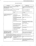
 Next
Next
w r l 15 10 TRUE TRACK BRAKE DIAGNOSIS CONDITION POSSIBLE CAUSE CORRECTION No br 1 1i Syst completely Remove eomeeeurg to mtrouer cheek 1 l V but GW OK resistance across terminals AT SPEED SENSOR IKNPOFI W t h OT Engine CONNECTOR Should be infinite open If not runnmel Cont 6 replace itunes Controller faulty Replace controller No brake light System completely Loss of ground connection to Check black ground wire connection from inoperative and no exercise cycle controller controller to instrument panel ignition switch on or engine running Controller connector not plugged Plug in controller into hamess Solenoid valve will not operate Disconnect solenoid lead Remove solenoid from modulator port Momentarily apply 12 volts to solenoid terminals and listen for solenoid core movement sharp click lf inoperative replace solenoid Apply 12 volts to solenoid terminals for 2 3 seconds and observe if vacuum leak stops after solenoid clicks with engine running If vacuum leak does not stop replace solenoid Modulator will not cycle when Check for vacuum at modulator If engine engine is started vacuum is not present at modulator check for restricted hose check valve at connec tor or for vacuum leaks If OK replace modulator Controller faulty Replace controller Brake light comes on after a 2 5 Speed sensor leads open Check speed sensor connector s for secure second delay System completely connection inoperative but exercise cycle OK Disconnect connector s and check continu Ignition switch on or engine ity acrox sensor terminals should be running 1000 2500 ohms If not replace sensor s Remove connector s to controller and check resistance across terminals E and F J and K at hamess connector with the speed sensor connector s reconnected should be 1000 2500 ohms if open replace harness Speed sensor lead s shorted to Disconnect speed sensor connector s and ground check continuity of speed sensor terminals to ground If any terminal is grounded re place speed sensor Remove connector s to controller Check continuity of speed sensor connector tenni nals to ground If any terminal E F J or K is grounded replace hamess Modulator travel switch open Remove connector from modulator travel I switch tenninal Check for 0 10 ohm resis tance resding from terminal to ground If c out of limits replace modulator E