Jeep Parts Wiki | Ford Parts Wiki
Home | Search | Browse | Marketplace | Messages | FAQ | Guest
Prev

 Next
Next
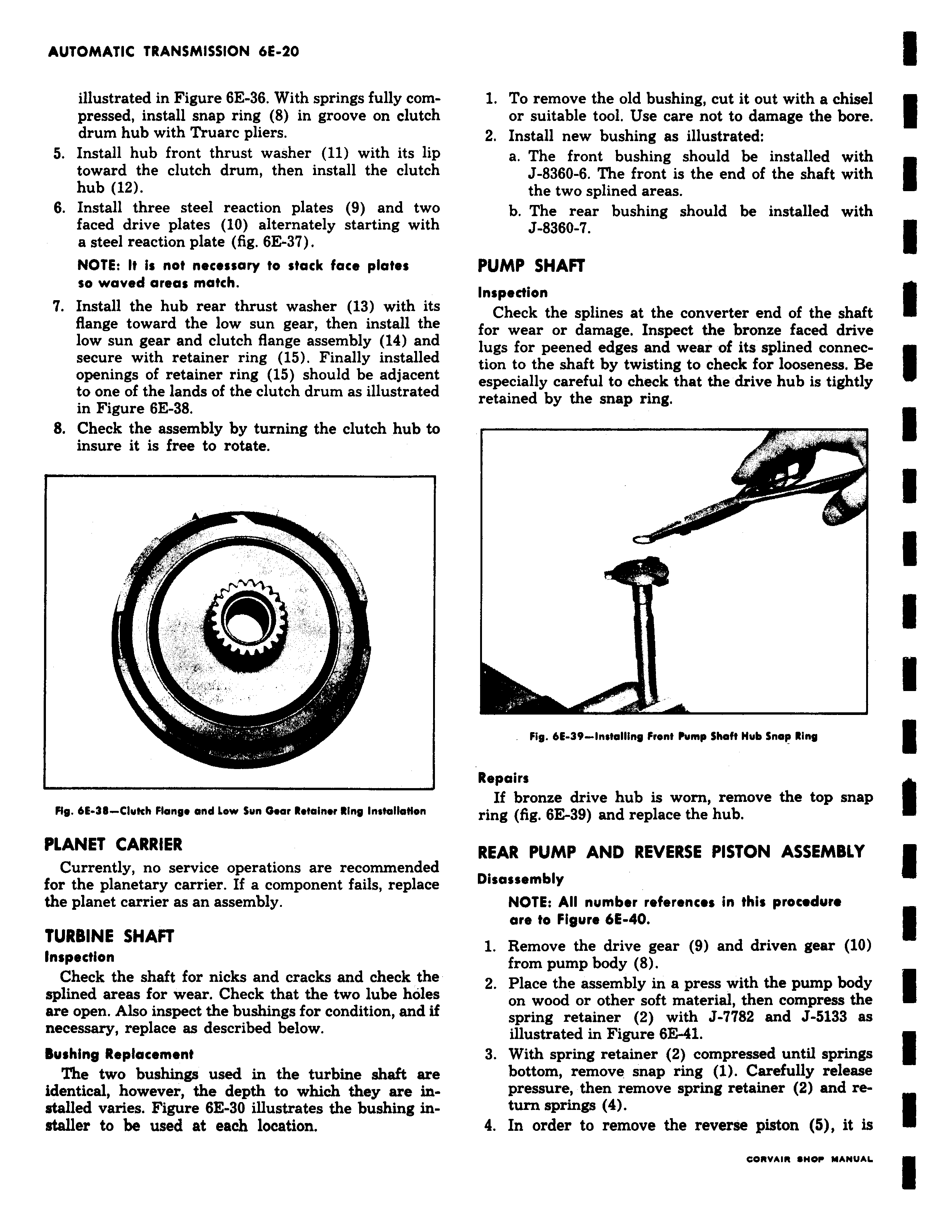
illustrated in Figure 6E 36 With springs fully compressed install snap ring 8 in groove on clutch drum hub with Truarc pliers 5 Install hub front thrust washer 11 with its lip toward the clutch drum then install the clutch hub 12 6 Install three steel reaction plates 9 and two faced drive plates 10 alternately starting with a steel reaction plate fig 6E 37 NOTE It is not necessary to stack face plates so waved areas match 7 Install the hub rear thrust washer 13 with its flange toward the low sun gear then install the low sun gear and clutch flange assembly 14 and secure with retainer ring 15 Finally installed openings of retainer ring 15 should be adjacent to one of the lands of the clutch drum as illustrated in Figure 6E 38 8 Check the assembly by turning the clutch hub to insure it is free to rotate I v Fig 6E 36 Clufch Flange and Low Sun Gear Retainer Ring Installation PLANET CARRIER Currently no service operations are recommended for the planetary carrier If a component fails replace the planet carrier as an assembly TURBINE SHAFT Inspection Check the shaft for nicks and cracks and check the splined areas for wear Check that the two lube holes are open Also inspect the bushings for condition and if necessary replace as described below Bushing Replacement The two bushings used in the turbine shaft are identical however the depth to which they are installed varies Figure 6E 30 illustrates the bushing installer to be used at each location 1 To remove the old bushing cut it out with a chisel or suitable tool Use care not to damage the bore 2 Install new bushing as illustrated a The front bushing should be installed with J 8360 6 The front is the end of the shaft with the two splined areas b The rear bushing should be installed with J 8360 7 Check the splines at the converter end of the shaft for wear or damage Inspect the bronze faced drive PUMP SHAFT Inspection g spline connection n to the shaft by twisting to check for looseness Be especially careful to check that the drive hub is tightly retained by the snap ring Fig 611 39 Installing Front Pump Shaft Hub Snap Ring Repairs If bronze drive hub is worn remove the top snap ring fig 6 39 and replace the hub REAR PUMP AND REVERSE PISTON ASSEMBLY Disassembly NOTE All number references in this procedure are to Figure 6E 40 1 Remove the drive gear 9 and driven gear 10 from pump body 8 2 Place the assembly in a press with the pump body on wood or other soft material then compress the spring retainer 2 with J 7782 and J 5133 as illustrated in Figure 6E41 3 With spring retainer 2 compressed until springs bottom remove snap ring 1 Carefully release turn springs 4 order 4 In piston

 Next
Next