Jeep Parts Wiki | Ford Parts Wiki
Home | Search | Browse | Marketplace | Messages | FAQ | Guest
|
Body Service Manual August 1964 |
|
Prev

 Next
Next
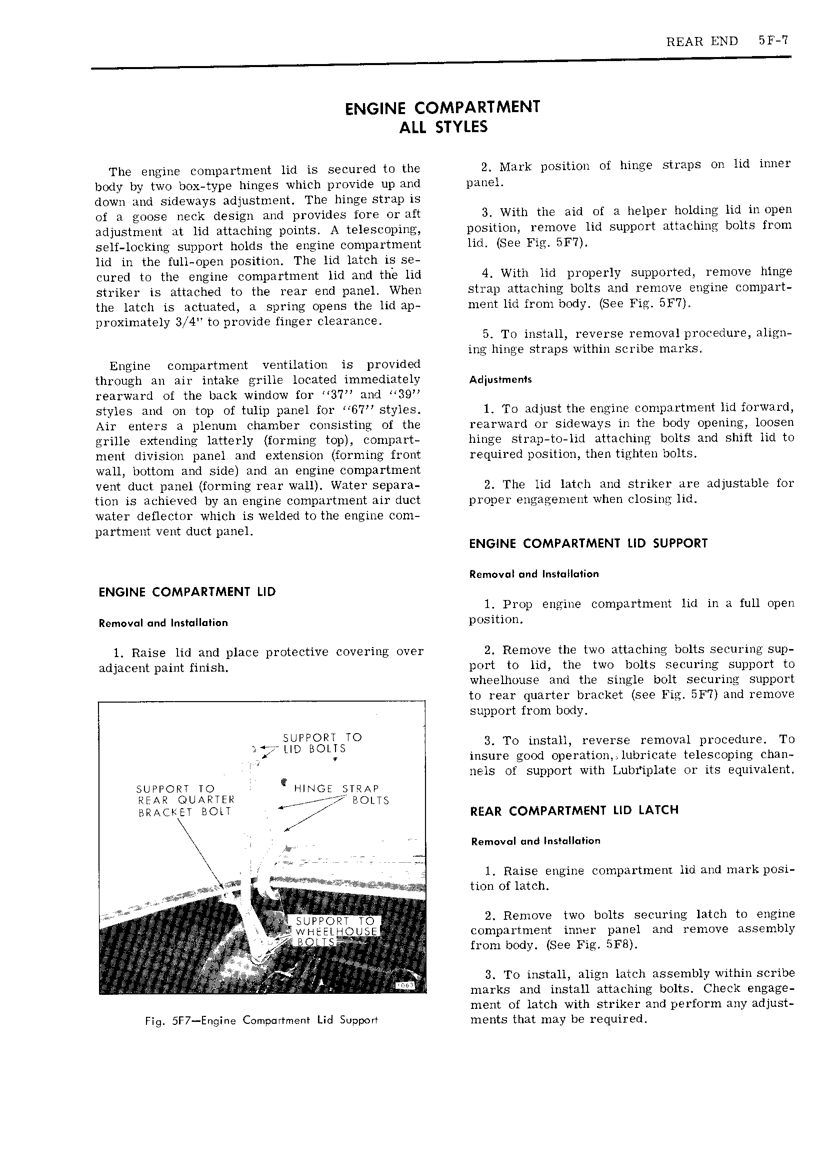
REAR END 5F 7 ENGINE COMPARTMENT ALL STYLES The engine compartment lid is secured to the 2 Mark position ot hinge straps on lid inner body by two box type hinges which provide up and panel down and sideways adjustment The hinge strap is of a goose neck design and provides fore or aft 3 With the aid of a helper holding lid in open adjustment at lid attaching points A telescoping position remove lid support attaching bolts from self locking support holds the engine compartment lid See Fig BF7 lid in the full open position The lid latch is se cured to the engine compartment lid and the lid 4 With lid properly supported remove hinge striker is attached to the rear end panel When strap attaching bolts and remove engine compart the latch is actuated a spring opens the lid ap ment lid from body See Fig 5F7 proximately 3 Ll to provide finger clearance 5 To install reverse removal procedure align ing hinge straps within scribe marks Engine compartment ventilation is provided through an air intake grille located immediately Adjusvmenis rearward of the back window for 37 and 39 styles and on top of tulip panel for 6 7 styles l To adjust the engine compartment lid forward Air enters a plenum chamber consisting of the rearward or sideways in the body opening loosen grille extending latterly forming top compart hinge strap to lid attaching bolts and shift lid to ment division panel and extension forming front required position then tighten bolts wall bottom and side and an engine compartment vent duct panel forming rear wall Water separa 2 The lid latch and striker are adjustable for tion is achieved by an engine compartment air duct proper engagement when closing lid water deflector which is welded to the engine com partment vent duct panel ENGINE COMPARTMENT LID SUPPORT Removal nd InsI Il Ii n ENGINE COMPARTMENT LID l Prop engine compartment lid in a full open Removal and Instullatian position l Raise lid and place protective covering over 2 Remove the two attaching bolts securing sup adjacent paint finish port to lid the two bolts securing support to wheelhouse and the single bolt securing support to rear quarter bracket see Fig SF7 and remove support from body 4 iijDPPB PLiSTO 3 To install reverse removal procedure T0 f insure good operation lubricate telescoping chan nels of support with Lubriplate or its equivalent SUPPORT TO HINGE STRAP PEAR GUAPTER ejiff BOLTS Ramona ana nmanneoaen iw 1 Raise engine compartment lid and mark posi g Q i w tion of latch l i V 2 e gnppg 2 Remove two bolts securing latch to engine ij I i compartment inner panel and remove assembly ij 1 i B U gi from body See Fig 5F8 i tp 1 t i T J gl it 3 T0 install align latch assembly within scribe K l marks and install attaching bolts Check engage ment of latch with striker and perform any adjust Fig 5F7 Engine Compartment Lid Support ments that may be required

 Next
Next