Jeep Parts Wiki | Ford Parts Wiki
Home | Search | Browse
|
Body Service Manual August 1964 |
|
Prev
 Next
Next
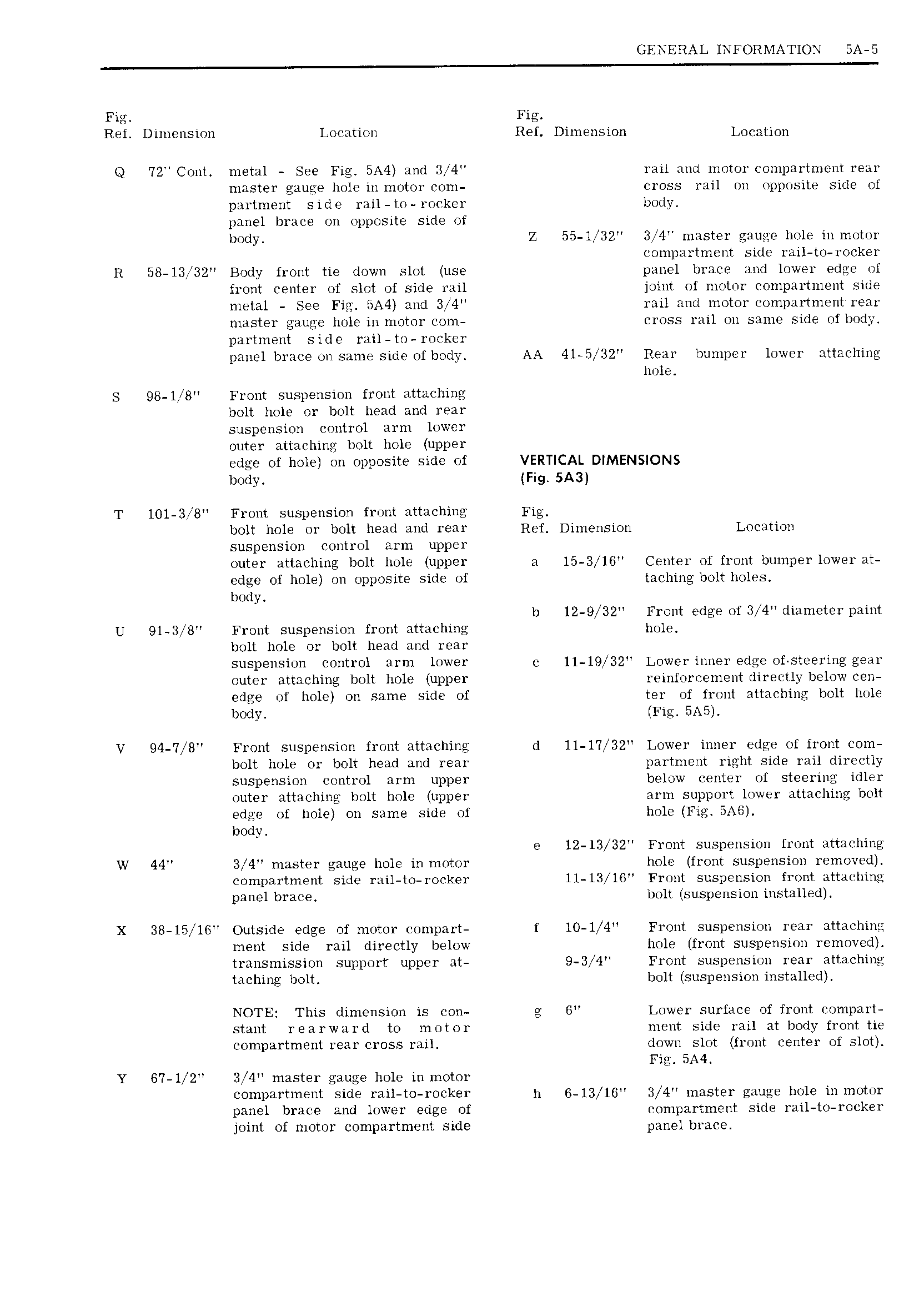
GENERAL INFORMATION 5A 5 Fig Fig Ref Dimension Location Ref Dimension Location Q 72 Cont metal See Fig BA4 and 3 4 rail and motor compartment rear master gauge hole i11 motor com cross rail o11 opposite side of partment side rail to rocker body panel brace on opposite side of body Z 55 l 32 3 4 master gauge hole in motor compartment side rail to rocker R 58 l3 32 Body front tie down slot use panel brace and lower edge of front center of slot of side rail joint of motor compartment side metal See Fig BA4 and 3 4 rail and motor compartment rear master gauge hole in motor com cross rail on same side of body partment side rail to rocker panel brace on same side of body AA 4l 5 32 Rear bumper lower attaching hole S QB l B Front suspension front attaching bolt hole or bolt head and rear suspension control arm lower outer attaching bolt hole upper edge of hole on opposite side of VERTICAL DIMENSIONS body Fig SA3 T lOl 3 8 Front suspension front attaching Fig bolt hole or bolt head and rear Ref Dimension Location suspension control arm upper outer attaching bolt hole upper a 15 3 l6 Center of front bumper lower at edge of hole 011 opposite side of taching bolt holes body b 12 9 32 Front edge of 3 14 diameter paint U 91 31 8 Front suspension front attaching hole bolt hole or bolt head and rear suspension control arm lower wr 11 l9 1 32 Lower inner edge of steering gear outer attaching bolt hole upper reinforcement directly below cen edge of hole on same side of ter of front attaching bolt hole body Fig BA5 V 94 I 8 Front suspension front attaching d ll I 32 Lower inner edge of front com bolt hole or bolt head and rear partment right side rail directly suspension control arm upper below center of steering idler outer attaching bolt hole upper arm support lower attaching bolt edge of hole on same side of hole Fig SA6 body e 12 13 32 Front suspension front attaching W 44 3 4 master gauge hole in motor hole front suspension removed compartment side rail to rocker 11 13 l6 Front suspension front attaching panel brace bolt suspension installed X 38 15 16 Outside edge of motor compart f l0 1 4 Front suspension rear attaching ment side rail directly below hole front suspension removed transmission support upper at 9 3 4 Front suspension rear attaching taching bolt bolt suspension installed NOTE This dimension is con g G Lower surface of front compart stunt rearward to motor ment side rail at body front tie compartment rear cross rail down slot front center of slot SA4 Y 67 l 2 3 4 master gauge hole in motor compartment side rail to rocker h 6 13 1G 3 4 master gauge hole i11 motor panel brace and lower edge of compartment side rail to rocker joint of motor compartment side panel brace