Jeep Parts Wiki | Ford Parts Wiki
Home | Search | Browse
|
Body Service Manual August 1964 |
|
Prev

 Next
Next
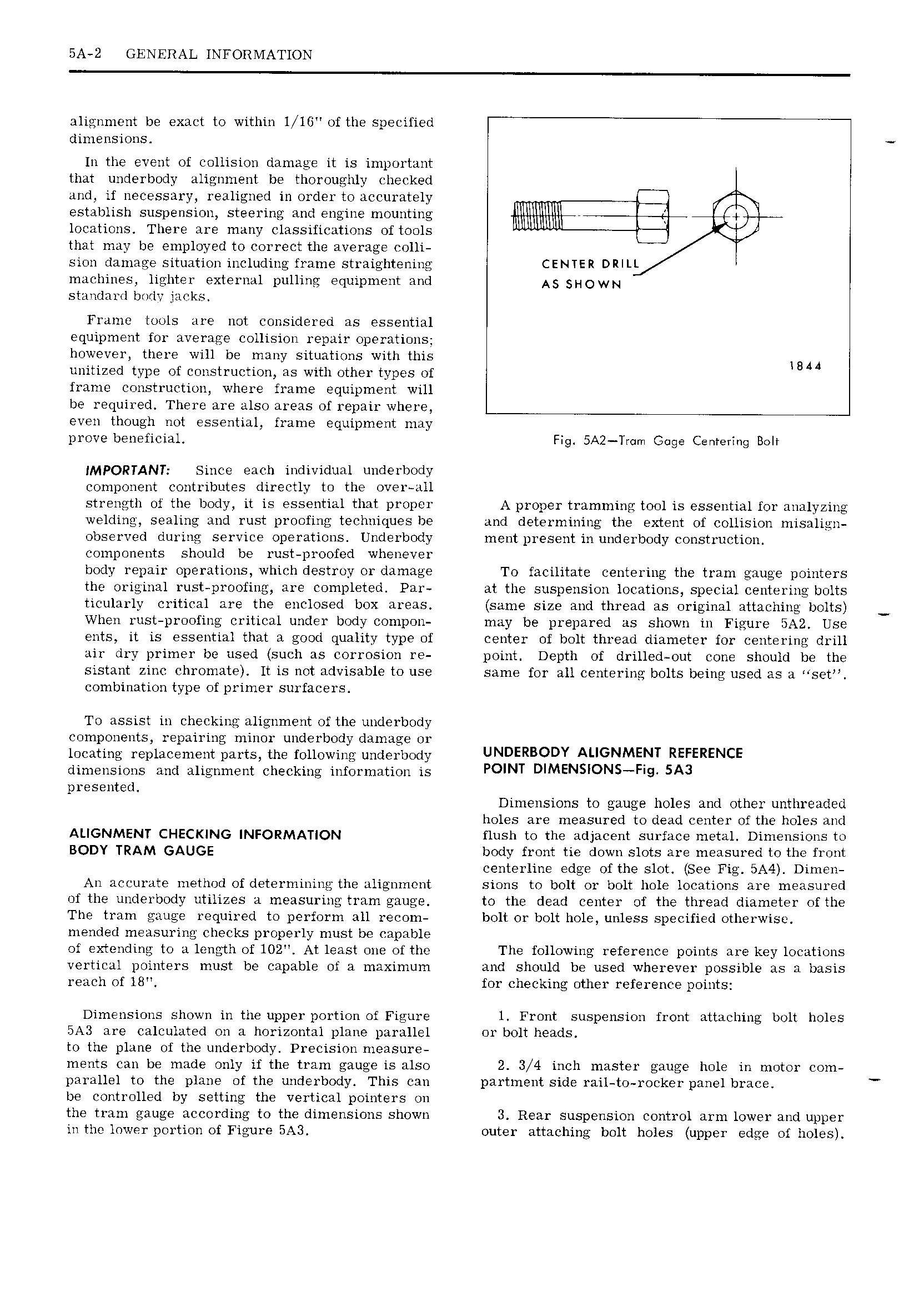
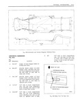
5A 2 GENERAL INFORMATION alignment be exact to within l 15 of the specified dimensions In the event of collision damage it is important that unclerbody alignment be thoroughly checked and if necessary realigned in order to accurately establish suspension steering and engine mounting locations There are many classifications of tools that may be employed to correct the average colli sion damage situation including frame straightening CENTER DRILL machines lighter external pulling equipment and A5 SHOWN standard body jacks Frame tools are not considered as essential equipment for average collision repair operations however there will be many situations with this WA4 unitized type of construction as with other types of frame construction where frame equipment will be required There are also areas of repair where even though not essential frame equipment may prove beneficial Fig SAZ Trom Gage Cenrering Bolt IMPORTANT Since each individual underbody component contributes directly to the over all strength of the body it is essential that propcr A proper tramming tool is essential for analyzing welding sealing and rust proofing techniques be and determining the extent of collision misalign observed during service operations Underbody ment present in underbody construction components should be rust proofod whenever body repair operations which destroy or damage To facilitate centering the tram gauge pointers the original rust proofing are completed Par at the suspension locations special centering bolts ticularly critical are the enclosed box areas same size and thread as original attaching bolts When rust proofing critical under body compon may be prepared as shown in Figure BA2 Use ents it is essential that a good quality type of center of bolt thread diameter for centering drill air dry primer be used such as corrosion re point Depth of drilled out cone should be the sistant zinc chromate It is not advisable to use same for all centering bolts being used as a sct combination type of primer surfacers To assist in checking alignment of the underbody components repairing minor underbody damage or locating replacement parts the following underbody UNDERBODY AI IGNMENT REFERENCE dimensions and alignment checking information is POINT DIMENSION FI9 SA3 presented Dimensions to gauge holes and other unthreaded holes are measured to dead center of the holes and ALIGNMENT CHECKING INFORMATION flush to the adjacent surface metal Dimensions to BODY TRAM GAUGE body front tie down slots are measured to the front centerline edge of the slot See Fig BA4 Dimen An accurate method of determining the alignment sions to bolt or bolt hole locations are measured of the underbody utilizes a measuring tram gauge to the dead center of the thread diameter ofthe The tram gauge required to perform all recom bolt or bolt hole unless specified otherwise mended measuring checks properly must be capable of extending to a length of 102 At least one of the The following reference points are key locations vertical pointers must be capable of a maximum and should be used wherever possible as a basis reach of 18 for checking other reference points Dimensions shown in the upper portion of Figure l Front suspension front attaching bolt holes BA3 are calculated on a horizontal plane parallel or bolt heads to the plane of the underbody Precision measure ments can be made only if the tram gauge is also 2 3 4 inch master gauge hole in motor com parallel to the plane of the underbody This can partment side rail to rocker panel brace be controlled by setting the vertical pointers on the tram gauge according to the dimensions shown 3 Rear suspension control arm lower and upper in the lower portion of Figure 5A3 outer attaching bolt holes upper edge of holes

 Next
Next