Jeep Parts Wiki | Ford Parts Wiki
Home | Search | Browse | Marketplace | Messages | FAQ | Guest
Prev

 Next
Next
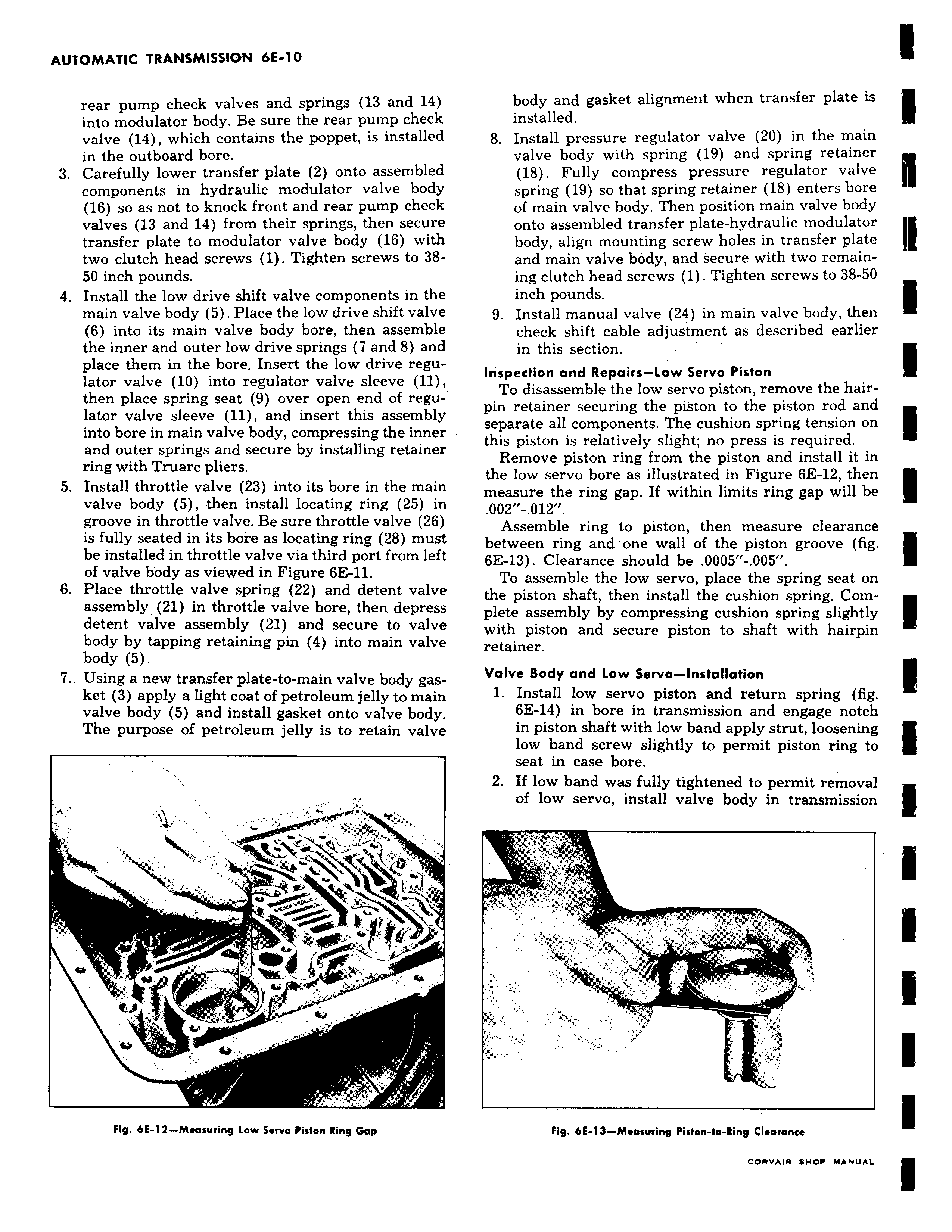
rear pump check valves and springs 13 and 14 into modulator body Be sure the rear pump check valve 14 which contains the poppet is installed in the outboard bore 3 Carefully lower transfer plate 2 onto assembled components in hydraulic modulator valve body 16 so as not to knock front and rear pump check valves 13 and 14 from their springs then secure transfer plate to modulator valve body 16 with two clutch head screws 1 Tighten screws to 3850 inch pounds 4 Install the low drive shift valve components in the main valve body 5 Place the low drive shift valve 6 into its main valve body bore then assemble the inner and outer low drive springs 7 and 8 and place them in the bore Insert the low drive regulator valve 10 into regulator valve sleeve 11 then place spring seat 9 over open end of regulator valve sleeve 11 and insert this assembly into bore in main valve body compressing the inner and outer springs and secure by installing retainer ring with Truarc pliers 5 Install throttle valve 23 into its bore in the main valve body 5 then install locating ring 25 in groove in throttle valve Be sure throttle valve 26 is fully seated in its bore as locating ring 28 must be installed in throttle valve via third port from left of valve body as viewed in Figure 6E 11 6 Place throttle valve spring 22 and detent valve assembly 21 in throttle valve bore then depress detent valve assembly 21 and secure to valve body by tapping retaining pin 4 into main valve body 5 7 Using a new transfer plate to main valve body gasket 3 apply a light coat of petroleum jelly to main valve body 5 and install gasket onto valve body The purpose of petroleum jelly is to retain valve c r f Fig 6E 12 Measuring Low Servo Piston Ring Gap body and gasket alignment when transfer plate is installed 8 Install pressure regulator valve 20 in the main valve body with spring 19 and spring retainer 18 Fully compress pressure regulator valve spring 19 so that spring retainer 18 enters bore of main valve body Then position main valve body onto assembled transfer plate hydraulic modulator body align mounting screw holes in transfer plate and main valve body and secure with two remaining clutch head screws 1 Tighten screws to 38 50 inch pounds 9 Install manual valve 24 in main valve body then check shift cable adjustment as described earlier in this section Inspection and Repairs Low Servo Piston To disassemble the low servo piston remove the hairpin retainer securing the piston to the piston rod and separate all components The cushion spring tension on this piston is relatively slight no press is required Remove piston ring from the piston and install it in the low servo bore as illustrated in Figure 6E 12 then measure the ring gap If within limits ring gap will be 002 012 Assemble ring to piston then measure clearance between ring and one wall of the piston groove fig 6E 13 Clearance should be 0005 005 To assemble the low servo place the spring seat on the piston shaft then install the cushion spring Complete assembly by compressing cushion spring slightly with piston and secure piston to shaft with hairpin retainer Valve Body and Low Servo Installation 1 Install low servo piston and return spring fig 6E 14 in bore in transmission and engage notch in piston shaft with low band apply strut loosening low band screw slightly to permit piston ring to seat in case bore 2 If low band was fully tightened to permit removal of low servo install valve body in transmission Fig 6E 13 Measuring Piston lo Ring Clearance

 Next
Next