Jeep Parts Wiki | Ford Parts Wiki
Home | Search | Browse | Marketplace | Messages | FAQ | Guest
|
Body Service Manual August 1964 |
|
Prev

 Next
Next
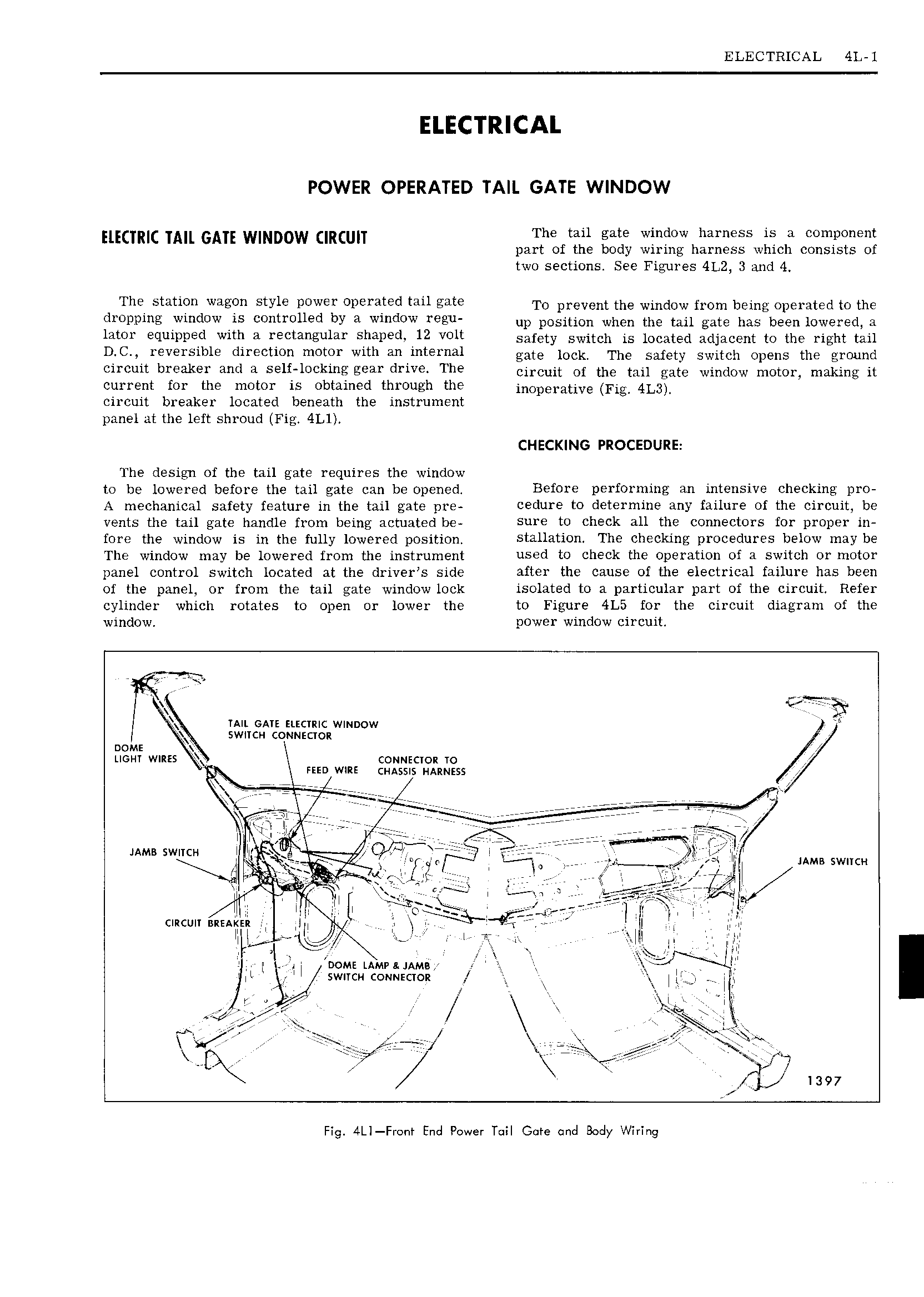
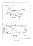
ELECTRICAL 4L l POWER OPERATED TAIL GATE WINDOW EIECTRIC TAIL GATE WINDOW CIRCUIT The tail gate window harness a component part of the body wiring harness which consists of two sections See Figures 4L2 3 and 4 The station wagon style power operated tail gate Te prevent the wiiidew imm being Operated ie the dmppmgi VmdO is controlled bY a mdO regu up position when the tail gate has been lowered a Mor equllrlaed with n rectangular Snarerlv 12 volt safety switch is ieeeten etijeeent to the right ten D C reversible direction motor with an internal eiaie Ieek The Safety Switch Opens the emuiad circuit breaker and a self locking gear drive The Circuit ei the taii gate Window meter makiiie ii current for the motor is obtained through the inoperative pie 4L3 circuit breaker located beneath the instrument panel at the left shroud Fig 4Ll CHECKING PROCEDURE The design of the tail gate requires the window to be lowered before the tail gate can be opened Before performing an intensive checking pro A meghgmiggl safety feature in the tai gate pre ceclure to determine any failure of the circuit be vents the tan gate nanrue tt ent being actuated be Sure to check all the connectors for proper in fore the window is in the fully lowered position Stilllation The checking procedures below may be The window may be lowered from the instrument used to check the operation of a switch or motor panel control switch located at the driver s side after the cause of the electrical failure has been of the panel or from the tail gate window lock isolated to a particular part of the circuit Refer cylinder which rotates to open or lower the to Figure 4L5 for the circuit diagram of the window power window circuit r r a TAIL GATE ELECTRIC WINDOW It SWITCH CONNECTOR 0ME x LIGHT WIRES CONNECTOR TO FEED WIRE CHASSIS wumzss e i 7 W C 7er 7 r I rx or or rrse e r rr r r77 een a ee eaao It rrne l iIE T i E I E V reee I II I tI I JAMB swncw I I Fi Q 1 g t I ja IIJI HMB SWITCH YY E v Y i ri r zi V I 2 l II II I J i 1 itil Ii I I r 3 r II lt I I cmcun nerkgn Ii ite i X II II I his lll I I III I III I o li DOME LAIvIvu JAM I Ni Il swIIcM couuscrok I g iii I III Ir I ir I u I 4 M ITB I r s L I e I II C T Oiii I oI z 1397 Fig 4LI Front End Power T iI Gore and Body Wiring

 Next
Next