Jeep Parts Wiki | Ford Parts Wiki
Home | Search | Browse | Marketplace | Messages | FAQ | Guest
|
Body Service Manual August 1964 |
|
Prev
 Next
Next
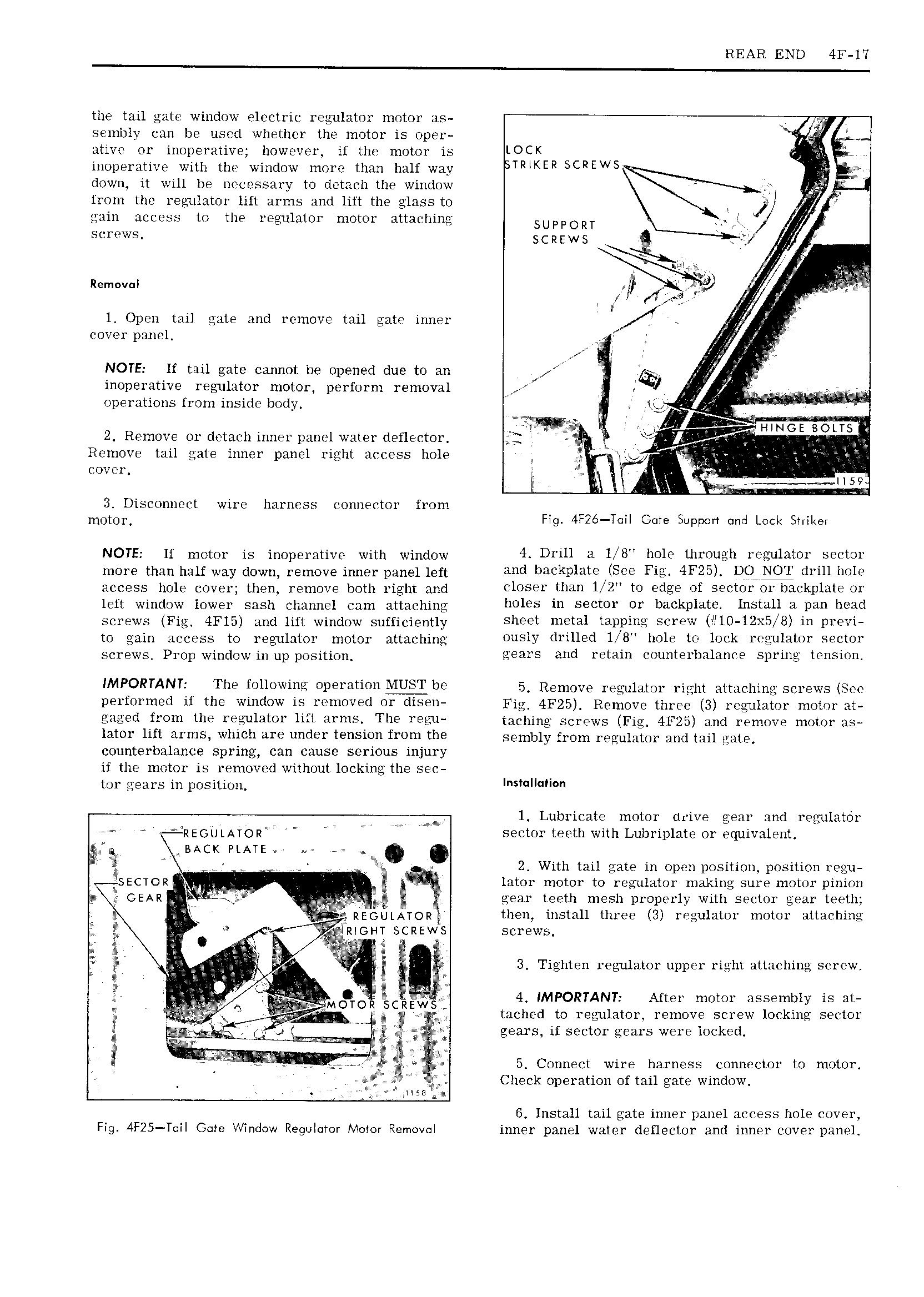
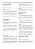
REAR END 4F IT the tail gate window electric regulator motor as senibly can be used whether the motor is oper ative or inoperative however if the motor is LOCK ir TES inoperative with the window more than halt way TRMER SLREWS down it will be iiecessary to detach the window l from the regulator lift arms and lift the glass to jl gain access to the regulator motor attaching SUPPORT S 1 WS scraews Nirl I L Q R I 4 nin fr p n emova U gf VA J 1 l Open tail gate and remove tail gate inner f fr cover panel f E ati NOTE lf tail gate cannot be opened due t0 an inoperative regulator motor perform removal A operations from inside body 1 P f l V tt l HINGE BOLTS 2 Remove or detach inner panel water detlector j 1 t t A Remove tail gate inner panel right access hole 3 V at r 1 cover i 2 lr tii 3 Disconnect wire harness connector from mOtO1 Fig 4F2 Tai Gate Support und Lack Sniker NOTE lf motor inoperative with window 4 DUH 3 L 8 l1Ol9 l l11 OL1 l1 1 E Uliil01 Seeter more than nnii way dawn remove inner panel ian amt 1 1 1 1 te lsee 4F25 DQ NOT l1 11111 1e access hgln COVE than remove bmj right and closer than 1 2 to edge of sector or backplate or left window lower sash channel cam attaching l1Ol U1 Sector OT b t kDl 1 1 St 11 1 1te 1 screws Fig 41 15 and nn window sutricientiy Sheet metal tarpiue Screw lll10 12X5 8 ut previ 0 gain ACCESS fo gukl m mmm atmchjmy ously drilled l 8 hole to lock regulator sector gcrgwg prop wmdiyw muppOgjti gears and retain counterbalance spring tension IMFORTANTY The f0llOW111 0P 1 1t1011 MU T1 e 5 Remove regulator right attaching screws See performed if the window is rcnioved or cliseu Fig 4F25 Remove three 3 regulator motor at gaged from the regulator lift arms The regu melting screws Fig 4F25 and remove motor as lator lift arms which are under tension from the Spnybly 5 Om Nngumtm and Hu mln counterbalance spring can cause serious injury it the motor is removed without locking the sec tor gears in position l l ll 1 Lubricate motor drive gear and regulator REGULATOR sector teeth with Lubriplate or equivalent sAc PLATE 1 2 With tail gate in open position position regu r SECTOR ll lator motor to regulator making sure motor pinion GEAR iv Q J Q gear teeth mesh properly with sector gear teeth i REGULATOR then install three 3 regulator motor attaching i X7 fRiGHT SCREW5 screws 1 t Y ll 1 l i it IT li P M E 3 Tighten regulator upper right attaching screw 1 t g QV M O i scdnwtg 4 IMPORTANT After motor assembly is at gl in tached to regulator remove screw locking sector l i r t ge n s it sector gears were locked ml l w it i I lt l 5 Connect wire harness connector to motor I Check operation of tail gate window G Install tail gate inner panel access hole cover Fig 4F25 Tail Gate Window Regulator Motor Removal inner panel water deflector and inner cover pam l