Jeep Parts Wiki | Ford Parts Wiki
Home | Search | Browse | Marketplace | Messages | FAQ | Guest
|
Body Service Manual August 1964 |
|
Prev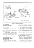
 Next
Next
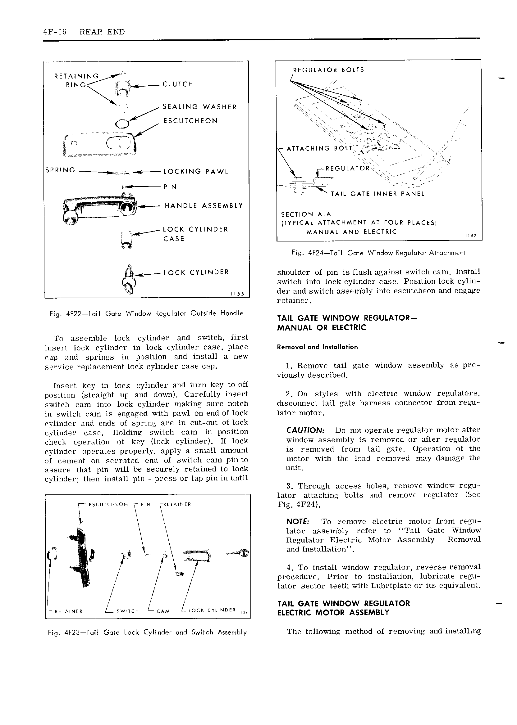
4F 16 REAR END RUNNING REGULATOR BOLTS Q RING l T E CLUTCH V zI EEEEEEE A SEALING WA5L TER rr q f ESCUTCHEON 7 r I ATTACHINC BOLT A s l RlNG e 4 Locl INo PAWL REGULATOR 7 Ir 2 LI j P N I gjjr iw V TAIL GATE INNER PANEL 1 I IANDLE ASSEMBLY SECTION ALA Y TYPICAL ATTACHMENT AT FOUR PLACES A 4 lOCK CYUNDER MANUAL AND ELECTRIC O Fig 4F24 T il Gme I indcw Regulumi Amiclsmem in j 4 LOCK CYLINDER shoulder of pin is flush against switch cam Install switch into lock cylinder case Position lock cylin M55 der and switch assembly into escutcheon and engage retainer F 4F22 T I Gr V d R II Ord I I dl Q I W eg S e S TAIL GATE wIND0w REGULATOR MANUAL OR ELECTRIC To assemble lock cylinder and switch first insert lock cylinder in lock cylinder case place Rem v I d Ins II i cap and springs in position and install a new service replacement lock cylinder case cap l Remove tail gate window assembly as pre viously described Insert key in lock cylinder and turn key to off position straight Llp and down Carefully insert 2 On styles with electric window regulators switch cam into lock cylinder making sure notch disconnect tail gate harness connector from regu in switch cam is engaged with pawl on end of lock lator motor cylinder and ends of spring are in cut out of lock cylinder case Holding switch cam in position CAUTION Do not operate regilator motor Mter check operation of key lock cylinder lf lock Window assembly is removed or after regulator cylinder operates properly apply 1 small amount is removed from tail gate Operation of the of cement on serrated end of switch cam pin to motor with the load removed may damage the assure that pin will be securely retained to lock unit cylinder then install pin press or tap pin in until 3 Through access holes remove window regu lator attaching bolts and remove regulator See E ESCUTCHEON T FIN XRETAINER H NOTE To remove electric motor from regu 7 lator assembly refer to Tail Gate Window Regulator Electric Motor Assembly Removal A 4 m i and Installation 2 4 To install window regulator reverse removal y Q procedure Prior to installation lubricate regu lator sector teeth with Lubriplate or its equivalent A g TAIL GATE WINDOW REGULATOR RETAINER WlTcH 7 cAM LOL k CYLINDER 5 Fig 4F23 T il Glare Lock Cylinder mid Switch Assembly The following method of removing and installing