Jeep Parts Wiki | Ford Parts Wiki
Home | Search | Browse | Marketplace | Messages | FAQ | Guest
Prev

 Next
Next
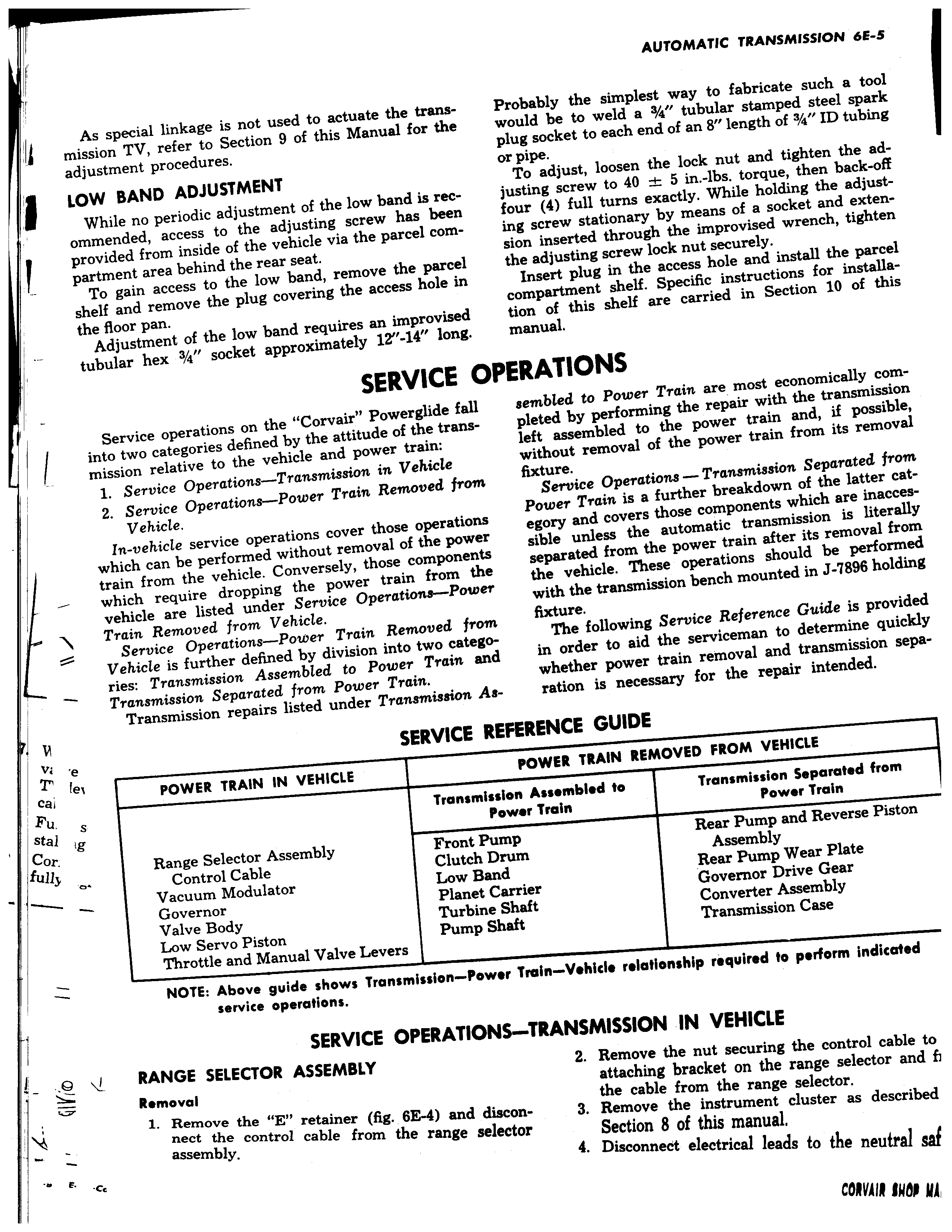
lr II As special linkage is not used to actuate the i mission TV refer to Section 9 of this Manual fc adjustment procedures LOW BAND ADJUSTMENT While no periodic adjustment of the low band i ommended access to the adjusting screw has provided from inside of the vehicle via the parcel partment area behind the rear seat To gain access to the low band remove the I shelf and remove the plug covering the access hi the floor pan Adjustment of the low band requires an imprc tubular hex 3 4 socket approximately 12 14 SERVI Service operations on the Corvair Powerglid into two categories defined by the attitude of the I mission relative to the vehicle and power train 1 Service Operations Transmission in Vehicl 2 Service Operations Power Train Removed Vehicle In vehicle service operations cover those oper which can be performed without removal of the train from the vehicle Conversely those comp which require dropping the power train froi vehicle are listed under Service Operations i Train Removed from Vehicle Service Operations Power Train Removed Vehicle is further defined by division into two e ries Transmission Assembled to Power Trail Transmission Separated from Power Train Transmission repairs listed under Transmisaic w e SERVIC fei cai POWER TRAIN IN VEHICLE s Tram 4al v or Range Selector Assembly Fron a Control Cable Clutc Vacuum Modulator Low Governor Plan Valve Body Turb Low Servo Piston Pum Throttle and Manual Valve Levers NOTE Above guide shows Transmission P4 service operations SERVICE OPERATIC RANGE SELECTOR ASSEMBLY Removal 1 Remove the E retainer fig 6E 4 and d nect the control cable from the range se assembly E cc sans Probably the simplest way to fabricate such a r the would be to weld a 3 4 tubular stamped steel s plug socket to each end of an 8 length of 3 4 ID tu or pipe To adjust loosen the lock nut and tighten the rec justing screw to 40 5 in lbs torque then bacl been four 4 full turns exactly While holding the ad com ing screw stationary by means of a socket and ea sion inserted through the improvised wrench tig arcel the adjusting screw lock nut securely tle in Insert plug in the access hole and install the p compartment shelf Specific instructions for inst vised tion of this shelf are carried in Section 10 of long manual E OPERATIONS e fall sembled to Power Train are most economically I rans pleted by performing the repair with the transmi left assembled to the power train and if pos without removal of the power train from its reYr from fixture Service Operations Transmission Separated Power Train is a further breakdown of the latter ations egory and covers those components which are ina ower sible unless the automatic transmission is lite inents separated from the power train after its removal n the the vehicle These operations should be perfo ower with the transmission bench mounted in J 7896 ho from fixture atego The following Service Reference Guide is pro t and in order to aid the serviceman to determine qu whether power train removal and transmission in As ration is necessary for the repair intended E REFERENCE GUIDE POWER TRAIN REMOVED FROM VEHICLE mission Assembled to Transmission Separated from Power Train Power Train Pump Rear Pump and Reverse Pisto h Drum Assembly Band Rear Pump Wear Plate A Carrier Governor Drive Gear ine Shaft Converter Assembly Shaft Transmission Case iwer Train Vehid relationship required to perform indicated INS TRANSMISSION IN VEHICLE 2 Remove the nut securing the control cable i attaching bracket on the range selector and the cable from the range selector iscon 3 Remove the instrument cluster as describe lector Section 8 of this manual 4 Disee e f

 Next
Next